
Complete Synth Build Guide For Beginners

The Code / Making Of
(If you're not interested in the coding, feel free to skip these articles!)
Part 1 - MIDI and Wav select switch
Part 2 - Envelope Attack & Release
Upgrade to the original Code:

1. What You'll Need
Let's start first with all the components that we'll need, commonly known as a bill of materials, or BOM (don't say that in an airport).
I've chosen most of the components from Tayda electronics in Thailand; they're cheap and have always been reliable with parcels making it to me in Germany in about a week or so. They also have monthly 15% off discounts, so keep an eye out on their Facebook page for that.
Some components that I couldn't find I've posted eBay listings for, I'm sure you'll be able to find the equivalent parts listings in your own country, or perhaps you have local parts shops?
(please let me/others know if you spot a mistake)
Tayda Parts:

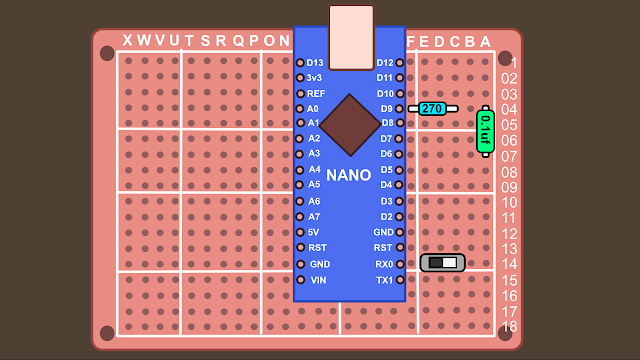
x1 Arduino Nano with usb cable $3.69 The 'brain' of our synth

It was pointed out to me that this pot is silent until the last few millimetres and then suddenly the volume is full. Try using a 100k version like this one instead.
x1 1M Ohm Logarithmic Taper Pot $0.50 Audio volume pot (use 100k)

x6 10K Ohm Linear Taper Pot $0.50 ($3) Synth control pots

x4 220 Ohm 1/4W 5% Resistor $0.01 ($0.10) Resistors (10 pack)
x2 270 Ohm 1/4W 5% Resistor $0.01 ($0.10) Resistors (10 pack)
x1 100 Ohm 1/4W 5% Resistor $0.01 ($0.10) Resistors (10 pack)
x1 470 Ohm 1/4W 5% Resistor $0.01 ($0.10) Resistors (10 pack)


x1 3.5mm Mono Audio Jack $0.12 Audio Out jack
**Update** This above jack was not long enough to fit the 3mm-deep Perspex sheet, replaced with a slightly longer version;
x1 3.5mm Mono Audio Jack $0.22 Audio Out jack
Tip: You can also use a larger guitar audio jack if you'd prefer.

x1 0.1uf (100nf) Poly Cap $0.10 Poly Capacitor for audio

x1 Proto board $0.99 Solder board for parts to sit on
**Update** Unfortunately Tayda didn't sell the same board as I used so this one was used as a replacement. It's a lot bigger than the 5cm x 7cm board I used, but it's possible to trim it down: What you can do is get a box-knife and a metal ruler and score down the sides you want cut off, then place it over the edge of a table and snap it off. Use a marker to add the numbering and characters. If you don't want to do this, have a search on eBay for a more similar board. Here's a link to banggood selling some (another site I use with much success), however it looks like the numbers / and letters are reversed from the board I used, so you might want to search further. Here's an eBay link to similar boards


x5 AWG hook up wire Red $0.10 ($0.50) Red wire (150cm)
x5 AWG hook up wire White $0.10 ($0.50) White wire (150cm)
Ebay parts (Google it & you might find better prices closer to you/store pickup possibilities etc). If the listings have ended, search by component name and if it looks like the photo shown here, you should be OK;
Tip: You can get parts from China really really cheaply but delivery times of a month or more are very common. Also I guess for me personally, maybe 1 in 20 items tend to never arrive. Ebay has a great refund policy, but if something gets lost you might be looking at a two month wait until you get your hands on a part. If you've ordered the other parts from Tayda that will get to you in a week, you may find paying a little bit more from a same-country seller is well worth it.


x1 5pin MIDI Din Connector $0.99 Midi connector (ebay)
Parts Total: Tayda $11.92 / Ebay: $2.79
Total: $14.71 (without P&P)
Obviously postage will be different where you are in the world, but using the Tayda discount code hopefully everything will come to about $20... maybe $22, but I think it's better say $20 purely for the click-bait title. Let's agree to disagree OK?
What Else?
You'll need a soldering iron, solder, wire-cutters, pliers, wire-strippers (or use a sharp blade to expose wire). If you make a mistake soldering you might need a solder sucker. If you make lots of mistakes you might need a multi-meter. If you have none of these things, you can often pick them all up in starter kits.
The Case
You're free to put the synth in any case you like, although perhaps not metal as it can cause problems. Cheap options include an old lunch box or VHS tape case. Those dollar-store places often sell wooden boxes that can be used for a synth case. If you want to build a case like in the pictures, you might well have some spare wood lying about. If not, mine cost 3 Euros from an arts supply shop. You might be able to get them to cut it for you if you're lucky. I used a perspex sheet for the front panel, again from the arts shop for about 2 euros. I used a laser engraver for the panel text, but if you don't have one no worries, you could use a silver marker pen, or a label printer. Other things you might need are wood glue and a saw. Some screws? All things you should be able to get at a hardware store (or pay 3 times the price at an art supplies store).
 |
| No laser engraver? Here's another synth with labels from a label printer |
Knobs: There are loads of types to choose from, here's a Moog-style pack of ten for under 2 euros. Or some Dave Smith types for 1.40e.

2. The Code
Parts arrived? Lets start with testing the Arduino. First you'll need to download the Arduino IDE, which lets us upload the code from your computer to the Arduino Nano. Head over to the Arduino site and download the software for your pc/Mac/Linus computer. Go ahead and install it.
Installing Libraries
Update 19/09/24: Mozzi 2.0 has been released but might not work with the Helios code. I recommend using Mozzi V1 library for now, which you can find here: https://github.com/sensorium/Mozzi/tree/Mozzi_1
The code we are using requires some external libraries. Libraries let you use code that other people have written, letting you achieve stuff that you might not be able to do on your own (god knows I couldn't). Lets install them now.
To use MIDI with our synth, we need to download the library from 47 effects. Click the 'code' button, then download the zip file.
In the same way, go and download the zip file from the Mozzi synthesis library.
So now you should have two zip files waiting to be added to the Arduino software. Open the Arduino software, click 'Sketch' -> Include Library -> Add .Zip Library


Great, so now that's installed, lets connect the nano and upload some code. If you're having any problems, google it or use the Arduino forums. I promise you someone else will have had the same problem, and someone else will have the answer.
Connecting the Nano
Connect your Arduino Nano to the computer with the USB cable. Hopefully the software will auto-detect, but we still need to check. Go to Tools -> Board -> Arduino Nano. Now we choose the port (Tools->Port) and chose where the USB is plugged into (com1, com2, com3 etc). There's loads of tutorials online about this (aka better than I can write).
If you have problems uploading your code
You may need to install drivers, but hopefully not. The internet is your friend if you're having trouble. If you purchased your Arduino form Tayda, there's a link to drivers on the product page.
With the Nano plugged in, you're given the option to choose the processor (tools -> processor), you might find changing from atmega328p, to atmega328p(old boot-loader) will help.. To see if it's working, we'll upload our first software program (called a 'sketch' in Arduino speak)
Our First Sketch: Blink

Choose:
The program will now load into the Arduino software, you'll see this as code on the screen. Next we have to upload it to our Nano. Click the upload arrow on the software. The program will compile and then send it to your Arduino Nano (as long as the Nano is connected OK, and you've selected 'nano' as your board under tools etc). You'll get an error message if there's a problem (if so google about connecting an Arduino to your computer). If it's successful you'll see a 'done uploading' sign. The sketch 'Blink' turns the built in LED on the Nano light on and off every second. If you see the 'done uploading' message and the LED on the Nano flashing, you know your board is working. This is good!
Playing with the code
Just to show the computer who's boss, we'll change the code ever so slightly. In the blink sketch page, change the two parts of the code that say delay(1000) to delay(500). This will flash the light every half second. The code looks like this;
// the loop function runs over and over again forever
void loop() {
digitalWrite(LED_BUILTIN, HIGH); // turn the LED on (HIGH is the voltage level)
delay(1000); // wait for a second
digitalWrite(LED_BUILTIN, LOW); // turn the LED off by making the voltage LOW
delay(1000); // wait for a second
}
...Those bits that say '1000' you should change to '500' like this;
// the loop function runs over and over again forever
void loop() {
digitalWrite(LED_BUILTIN, HIGH); // turn the LED on (HIGH is the voltage level)
delay(500); // wait for a second
digitalWrite(LED_BUILTIN, LOW); // turn the LED off by making the voltage LOW
delay(500); // wait for a second
}
Upload the new code and check the LED. It should now be flashing twice as fast as before. Congratulations, you're now a programmer!
Upload the Synth Code
Good stuff, we now know the Arduino is working, so we can upload the synth code.
Head over to my github page and download the zip file. Extract the file on your computer; we need the file called helios4_6.ino (Arduino uses .ino files). Save it in a location you can find again on your computer (maybe in an documents/Arduino projects folder?).
Then go to the Arduino IDE software File -> Open, choose the .ino file and it should load into the Aduino IDE window. Now press the upload button... the magic the code should upload to your Arduino Nano. That's all we need to do the genie is now in the bottle. Now we can start putting the synth together.
Code Explanation
There's a great explanation over on the Mozzi website about a simple sketch - it explains the basic setup of how everything works. Also, because we installed the Mozzi library we can view lots of example code ->

The synth we are building started as one of these examples... I think the first one used was a Mozzi-Midi-Input sketch. Then combined that with an oscillator sketch. Then added the filter sketch, envelopes etc. Basically, all I've done is assign pots to commands in the code. It might seem daunting at first, but if I can do it, there's a very good chance you can too.
If you're interested in learning more, each part of the code is explained elsewhere in the following links, as is building the synth on a temporary breadboard;
...But you don't need to know any of this stuff to build the synth, although maybe in the future you might want to learn a little bit more (and help improve the code).
3. Electronics
Now we're going to put all the parts we ordered together... but we'll also quickly make the front panel (so we have something to hold the parts while we solder).
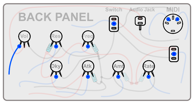
Front Panel

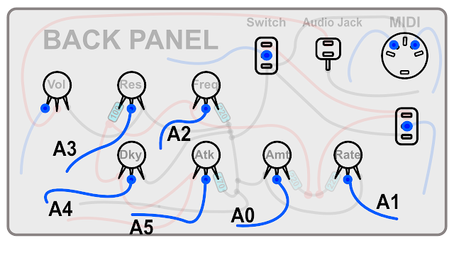
Panel Layout

Drilling the Panel
Drill bit sizes;

Then the back panel will look like this;

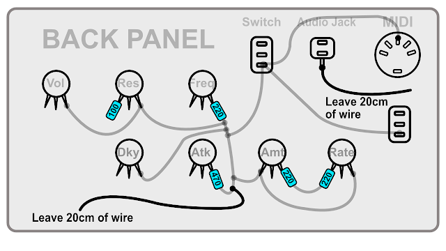
Start Soldering


A quick test (if you have a multi-meter)...
 |
| The green areas will beep, but not the red. |
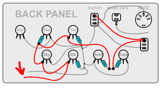
Back to Soldering

Now solder the next wires (again leave 20cm of wire on the one cable that isn't joined to anything). If you have a multimeter, check the Vol to Audio Jack. Then hold a connector to the two connections side of the resistor of the 'res', and see if you get a beep at freq, dky, atk, the switches and the middle of the Amt/Rate.


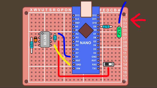
Making the proto-board:

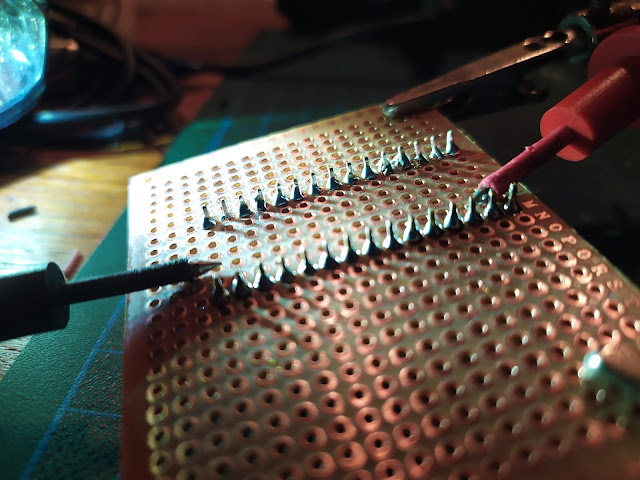
Now flip it over and solder all the legs to the board (the helping hands tool can come in handy here, or if not use a bit of tape to hold the Arduino down). Start with the corners to hold it into place. Make sure you don't accidentally solder any of the legs together:

Once soldered, using the multi-meter in continuity mode, check that none of the legs have accidentally been soldered together (put each multi-meter connector on the legs next to each-other and make sure there's no beep). If you hear a beep you may need to use a solder sucker to remove the excess solder. Sometimes the solder can get so close it looks like it's touching the other leg but it actually isn't.


Audio Out Section


 |
| Using the legs to jump to different areas |

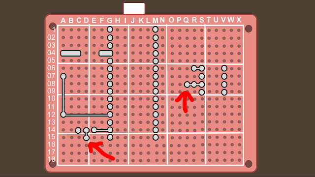
The MIDI circuit
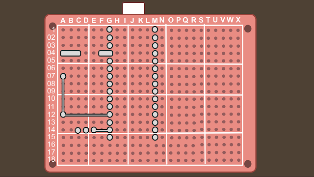


Easy right? Your board should now look like this:


Now we add a 220 ohm resistor to X7 and X11:


And then solder it together;


Solder them in place:

Joining The Front Panel to the Proto-Board
Then you solder it:


..solder it in place - make sure you get the correct pin soldered (look closely on the board for the direction of the connection:

That plugs in O12:


OK, so we're almost finished (the second time I've said that now) we just have a few wires from the pots left to solder.

We shall be using pins: A0, A1, A2, A3, A4 and A5. Why not A6 and A7 you may ask, well...

Connected underneath;

We're nearly Finished (This time I promise)
Ok, I forgot to get you to wire up the switches. Then we're finished. I promise. Let's do that now.We'll start with the LFO switch;

This wire connects to F10:

...and is soldered against the nano pin:

Now for the Wave Switch:


And then then solder to the nano pin:

 |
| Back view of synth - spaghetti junction! |
 |
| Finished view of the proto-board (Note: wire colors don't match examples) |
 |
| Your board should look a little like this (Note: might not exactly match examples) |
Now go get a beer.
Right, the synth is now complete - time now to give it a try. Is it working? Congratulations! Time for another beer. It's not working? Time to for some problem solving;
Troubleshooting Guide
Just remember that every part used is a potential problem waiting to spoil your fun, but hopefully we're going to get to the bottom of any faults. Lets break different problems down into categories;
1. Code:
The code definitely works (other people have confirmed this). Did you check the 'blink' sketch is working on your Arduino (the one where a light flashes on and off)? If not go back & read the code section of this guide again and get that working.
The switch is set incorrectly: Now that your synth is soldered, you maybe have to change the switch position (the one found on the proto-board) to get it to upload. From memory I believe the switch has to be pointing away from the nano to upload code, and closer to the nano to play the MIDI keyboard. Try reversing this if it's still not working.
Once the blink sketch is working, you can be fairly certain the problem isn't with the Arduino.
The only other problem you might have if you copy and paste the synth code and either you miss some of it, or your browser adds some extra (unseen) characters. Download the .ino file from my github (download everything as a zip). Then open the .ino file directly with the Arduino IDE. Once it's confirmed its uploaded OK, you can be pretty sure the code/Arduino are working correctly.
A few people have had problems with the midi switch. If you have a multimeter check for continuity on the switch legs. Only two pins should beep and one shouldn't. If all 3 beep that's the problem. If you don't have a multimeter you could desolder the switch and join the two connections closest to the Arduino.
2. MIDI connection
The proto-board switch is set correctly. You're playing the synth with a MIDI keyboard. Have you used this keyboard before and can confirm it works? How about the MIDI cable? And is it plugged in correctly? From the keyboard it should leave from the MIDI-OUT port and go into the DIY synth (which is MIDI-IN).
3. Power
You need to plug in the synth with the USB cable. Plug it into a mobile phone power supply, or maybe a laptop port (these can add noise to the audio). The Arduino should have a red power LED that lights up.
4. Is the Volume turned up/down?
It seems simple, but it has caught me out before! Also, there's a chance I've made you solder the volume pot in reverse, so maybe try turning it all the way down just in case.
5. There's a problem with this guide:
While I've tried really hard to write everything down without errors, it's entirely possible I've missed something. If you're having a problem leave a comment and I can update the guide with any fixes. Also leave a comment if you notice any mistakes. Thanks.
6. You've done something wrong:
Along with me making a mistake with the guide, this is probably the most likely cause for problems. We've made a lot of connections with the solder, and just one mistake could stop the whole thing. Check the following;
Dry Solder: Sometimes there can be 'dry' solder connections, where the part is connected but not really. You could try re-soldering/re-flowing these connections, or use a multi-meter in continuity mode to confirm they are good.
Accidental joins: It's possible some pins have accidentally been bridged while soldering. Again, use a multi-meter to check and de-solder any problems.
You've used different parts: If you know what you're doing then that's fine, but if you've used different parts without really knowing what they do, then this may have caused a problem. If you've used an Arduino Uno instead of a Nano, be aware the pins are in different places on the board (TX and RX pin I believe).
The Diode is the wrong way: Check the black line is facing the correct direction. The diode needs to face the correct way to work (while the resistors and capacitor we used on the board will work in either direction, known as having no 'polarity').
You've joined the wrong wires: Check check check! Look through the guide and confirm everything is correct.
The Audio jack isn't wired correctly: Check!
The LED light on the the Arduino Nano is showing midi is being sent, but I'm not getting Audio: If I had to guess it might be you've wired the audio pot wrong (or I've told you to do something wrong; other people have reported back success so hopefully not). If the midi light is lighting when you're pressing keys, then that part would appear to be working. Start with the simple things first: try turning the volume pot at different levels while playing the keys. Try this with all the knobs and buttons just to be sure. If that doesn't work, double check your connections around pin 9 of the Arduino nano... it should lead to a resistor and capacitor - this is where the audio leaves the Nano, then it goes to the volume pot, then to the audio jack. If you can't see a problem there then it's time to check the audio jack... the most likely candidate. Are the wires correct? Perhaps they need reversing? Are the jack connections the same in the photos? Perhaps the jack has been screwed in upside down (ie so the top leg is now bottom etc). Hopefully you'll find the problem. If you have a multi-meter you can check in continuity mode (the buzzer mode) that the bottom audio jack pin is going to ground... put one connector on the bottom jack, then the other connector on the Arduino nano pin that says 'gnd'. Hopefully it should beep.
7. There's a fault with one of your parts:
Maybe you left the soldering iron too close to a part for too long? I've never had it happen, but if you think you've mangled the soldering then look for burnt parts. Perhaps it was never working in the first place? While it's possible, it's also quite rare, even for dirt cheap parts. It's far more likely you've made a mistake somewhere else. If you've checked everything else is ok, you could start swapping out parts, or start checking voltages etc with the multi-meter. If you don't know how to do this, there are no doubt good YouTube videos/guides for you to learn from. You could also get into synth repair through this route, so while it's frustrating your synth isn't yet working, you are at least learning some new skills.
8. Wiggle
Try wiggling the wires to see if it suddenly starts working. That's the sign of a bad connection somewhere, or possibly a break in the wire.
9. Find a friend
If all else fails find someone else to help you fix it. If you don't know anyone personally you could try a local hack-space or friendly University department. If they know a little about electronics, you'll probably only have to show them the hand drawn schematic found at the top of this guide.
10. Try Running The Test Code
Tom Reid very nicely commented that he'd written some code to check the connections of the synth (copy & upload the blue code text into the Arduino IDE, and also open the serial monitor to view the results);
Great project and works well. I did knock together a short test program which checks all the switches and Pots. It gives an IDE monitor display so you can see the states and voltage. If you want a copy to post then you are more than welcome to post it.
Apologies for the delay - I need to add some comments into the code. Here is the code The test program checks the 2 switches and 6 controls. Also it generates a tone on the output socket. Compilied on IDE 1.8.42
>>>>>>>
/*
Test program for checking Pots, switches and Audio circuit
The program is designed to read the 6 volume controls and the 2 switches(LFO/WAV).
Yes I could have down this program cleaner with FOR loops, arrays etc - but it is only test program and took 20 minutes to knock up
Please feel to modify and improve on it.
Key elements the tester output will show on the monitor display
Note make sure switch is set to LOAD.
Switches
Wave Switch select0 Sq or Saw
LFO Switch select0 ON or OFF
Pots - set all Pots fully counter clockwise looking straight on to front panel
LFO RATE - Rate- clockwise increase volatage
LFO Rate - Amount - clockwies Voltage decreases
Filter-- Cutoff - clockwies Voltage decreases
Filter-- Res - clockwies Voltage increases
Envekope - Attack - clockwies Voltage decreases
Envelope - Release - Filter- clockwies Voltage increases
Audio output generates a Signal every
*/
//#include
float Volt0; // LFO Amount
float Volt1; // LFO Rate
float Volt2; // Filter cutoff
float Volt3; // Filter Res
float Volt4; // Envelope Release
float Volt5; // Envelope Attack
//wiring pins defined for the NANO version
int LFO;
int WAV;
int LFOPin = 3;
int WAVPin = 2;
void setup() {
// initialize serial communication at 9600 bits per second:
Serial.begin(9600);
pinMode(A0, INPUT);
pinMode(A1, INPUT);
pinMode(A2, INPUT);
pinMode(A3, INPUT);
pinMode(A4, INPUT);
pinMode(A5, INPUT);
pinMode(LFOPin, INPUT);
pinMode(WAVPin, INPUT);
pinMode(9,OUTPUT);
}
// the loop routine runs over and over again forever:
void loop()
{
// read the input on analog pin 0-5:
Volt0 = analogRead(A0);
Volt1 = analogRead(A1);
Volt2 = analogRead(A2);
Volt3 = analogRead(A3);
Volt4 = analogRead(A4);
Volt5 = analogRead(A5);
// Convert the analog reading (which goes from 0 - 1023) to a voltage (0 - 5V):
Volt0 = Volt0 * (5.0 / 1023.0); //LFO amount
Volt1 = Volt1 * (5.0 / 1023.0); // LFO Rate
Volt2 = Volt2 * (5.0 / 1023.0); //Filter Cutoff
Volt3 = Volt3 * (5.0 / 1023.0); //Filter Res
Volt4 = Volt4 * (5.0 / 1023.0); // Envelope Release
Volt5 = Volt5 * (5.0 / 1023.0); // Envelope Attack
LFO = digitalRead(LFOPin); // on/oFF
WAV = digitalRead(WAVPin); // Square or Saw wave
// print out the value
Serial.println(" LFO SW WAV SW LFO Rate LFO Amt Filter Cutoff Filter Res Env Rel Env Attack");
//Print switches
if ( LFO == 0) {
Serial.print(" OFF ");
}
else
{ Serial.print(" ON ");
}
if ( WAV == 0) {
Serial.print("SQR ");
}
else
{ Serial.print("SAW ");
}
Serial.print(Volt1);
Serial.print(" ");
Serial.print(Volt0);
Serial.print(" ");
Serial.print(Volt2);
Serial.print(" ");
Serial.print(Volt3);
Serial.print(" ");
Serial.print(Volt4);
Serial.print(" ");
Serial.print(Volt5);
Serial.println();
Serial.println();
tone(9,50,1000); //sound tone for short burst.-
delay(2000); // 2 seoond update on screen
// No test routing for the MIDI at this time - easy wiring so easy to troubleshoot
}
All good?
Hopefully you should have the synth up and running by now. If not, check the comments to see if any common problems have started to emerge. I'll try and help where I can, but obviously my time is limited.
4. Making a Case

You can make a case out of anything (VHS box!), but this is how I do it:
The wood used: mine cost 3 Euros from an arts supply shop in Berlin. It measures 9.0 x 250 x 500 mm. The same shop also sold perspex sheets for the front panel for 2 euros. These sheets measure 3 mm, 3.0 x 120 x 250 mm. Notice both the wood and perspex feature a 250mm measurement. This means if we cut the wood correctly it will already have a length exactly the same as the panel. This can save you some sawing, and you can also use the professionally cut sides at the front for a neater appearance (save your hack-saw work for the back!). If you don't have access to these supplies, I'm sure you can come up with you own method.
I used a laser engraver for the panel text, but if you don't have one no worries, you could use a silver marker pen, or a label printer. Other things you might need are wood glue and a saw. Some screws to join the panel to the wood. All things you should be able to get at a hardware store (or pay 3 times the price at an art supplies store).
Knobs: There are loads of types to choose from, here's a Moog-style pack of ten for under 2 euros. Or some Dave Smith types for 1.40e.
Ok, lets make the case:

12cm + 9mm + 9mm = 13.8cm
Tip: Depending how good you are with a saw, I'd cut each part 14cm long and then be prepared to sand down the excess.
Depth: I used 7cm as the depth of the wood. The nano and proto-board are about 5cm, so by using 7cm we give ourselves some room.
So you should now have wood like this:

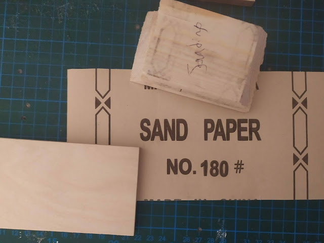
If you have the same wood skills as me, you'll probably have a few rough edges. You can use sanding paper or nail files to correct this:

Putting it all together:
We'll need wood glue. Remove all the components from the front panel and lay it down flat (or if you don't want to take the parts out: lay down four books and balance the panel in the middle, so it lays flat with the knobs hanging freely in the middle).
Stand the wooden sides around it and glue them together. You want a good fit where the panel meets the wood, so either hold it in place or use string and tie it together. Wood glue dries pretty quickly (5 - 10 min), so you won't get too bored. Think of it as birthing the synth.
Tip: You can buy a strap spanner to hold the wood tightly together for you, but it's a luxury item that you can do without.

Wipe away any excess glue (especially on the outside, where it can effect varnishing the wood). Now we cut a strip of 1cm-ish squared wood, cut into four 6cm pieces:
Tip: You can buy precut 1cm x 1cm wood from the store

Glue each of these pieces to the corners, making a good connection with the wood and also the front panel (these are where we'll screw in our synth panel):

When finished our case should look like this:

Tip: If you find the center of the perspex a little wobbly when playing the synth you can glue another 1cm piece to the center top or bottom of the case. Do this after you've finished so you don't get in the way of components.
Wipe away the excess glue.
Our case should now look like this:

Sand down any over-hanging edges if you like, or any glue that has leaked out.
The synth could be finished if you want to keep the wood looking natural, if not we can remove the panel and start to stain it.
I use a Mahogany stain like this;

The wood is thirsty, so you'll need maybe 3 or 4 coats. Add each layer evenly.


Apply a small amount with an old rag and finely distribute:
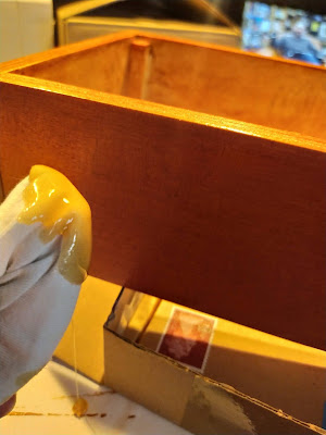


Tip: If you've missed some paint on the panel (like I have in the above picture on the LFO switch), you can still paint on the perspex, but just be aware it scratches easier this way.
 |
| Cable ties added. Still a bit of a mess! |

If you want a back cover you could cut some mdf board and screw it to the back. Mdf is an irritant to the lungs (possibly cancerous?), so wear a mask then wipe down your working area. Drill a hole for the usb port. You don't need a back cover (I probably won't bother for this build).

Thank you so much for sharing this!. I really love the passion you put into your builds and posts. I know how much work it needs to describe a project in this level of detail. You're a real inspiriation for the DIY community.
ReplyDeleteThanks Ben :-)
DeleteMany thanks for this build. It will make it onto my to-do list for next year (once I complete my current project).
ReplyDeleteI had a laugh at your $0.50 for the Taper Pots, until I re-read and saw that you purchased them through Tayda. Here is Australia the pots are $3 to $4 each, which makes it expensive when doing something like my 6ch Matrix Mixer.
I have just placed my first order with Tayda last week, so I was pleased to read that you are satisfied with them..
Looking forward to starting my Arduino Synth's in 2021
Tayda have always delivered a good experience for me, I hope for you to! Best of luck for your projects!
DeleteAny chance to update code to involve A6 and A7 pins? Thanks, Sl8v
ReplyDeleteIt would be easy to add full ADSR - if you read the code section about attack & decay you could probably figure out the code you need to add (especially if you compare that code with the previous version to see what changed). I'll probably make a more advanced Rev 2 version of this synth one day complete with this code, but if I added it now it would make the rest of this guide incomplete, and I'm a bit too busy to do all that right now!
DeleteI appreciate your work and detailed explanation, thank You! Will definitely try to build one. All parts are on the desk already. Some notes after reading code and process steps:
ReplyDelete1. Envelope string that puzzles me a bit:
envelope.setTimes(atkVal,60000,60000,dkyVal); // 60000 is so the note will sustain 60 seconds unless a noteOff comes
Looking at the mozzi's examples, the last value is actually Release, not Decay:
(envelope.setTimes(attack,decay,sustain,release_ms);). I'll try to expand code to full ADSR anyway...
2. 6N138 may be placed closer to +5V/GND pins to reduce wire links. I guess you tried to avoid clicking in audio, will check it myself.
3. For all soldering newbies (like me) I strongly suggest to use sockets for IC chips (6N138 and Arduino, why not). It won't hit the 20$ limit, but save from overheating the chips.
4. Maybe v2 will include delay code from mozzi just to ditch Zoom CDR (I have ZOOM processor, but other may not) from the audio chain.
5. Switch for firmware updating can be replaced with jumper, maybe this will be more clear to operate and save some penny :)
All in all, thanks for bringing me to Arduino world! Cheers, Sl8v
1. Yes that's me being silly - it's release not decay
Delete2. I think it was the 6n138 causing the clicking (probably midi data being sent). Either way, keeping the headphone jack connections further away/separate from it helped reduce this.
3. DIP sockets are a good idea, although I didn't think you could get them for a nano... just looked & apparently you can!
4. There's a delay example code included in the Mozzi examples, so it's very possible you could add this in. Just be aware it might be too much for the nano to run that + synth code. I noticed a lag in note response when I added too many features, so keeping it lean is a good idea - although saying that, I'm sure my code could be optimised a lot more so who knows. I'm mulling ideas for a Rev 2, and am thinking I'd add a PT2399 delay circuit so there would be no taxing of the Nano. Also thinking of having 2 nanos synced with midi, so you could have separate ADSR with two waveforms. Will try when I get some spare time.
5. Feel free to add whichever you think is best!
Cheers & I hope you have a trouble free build!
Were you able to get full ADSR working? Having trouble adding it to my code (figured out adding and setting up Sustain and Release, but not sure how to use them in the code)
DeleteI added ADSR to a version without a filter and LFO;
Deletehttps://github.com/gary909/ADSR-synth-V0.2
It appeared to be working, but I didn't have time to fully check. Will work on it some more after the holidays
Great project! Great write up! Many thanks!
ReplyDeleteI have three "nano every" boards sitting around waiting on a project. Do you know if they would work?
I ask because they won't work with the auduino granular synth/seq project you see online, but your included libraries are doing something different. Apparently they changed the ATmega328P to ATmega4809 and theres a subtle difference i can't remember at the moment.
DeleteI'm sorry but I really don't know. You could see if you can get the code to compile without an error? I would breadboard the headphone out part of the circuit and see if you can get some of the Mozzi project examples to play (you don't need a midi keyboard circuit for those)
DeleteThis comment has been removed by the author.
ReplyDeleteNice work! I'm always looking for fun Arduino or Pi father/son projects. I would appreciate a demo WITHOUT using the reverb pedal, just raw. Otherwise, it's a $150 synth. Thanks.
ReplyDeleteThanks! I only have a phone video: https://bloghoskins.blogspot.com/2020/09/helios-one-synth-audio-demo.html
DeleteWhat a great project. I really like the work you have done, both on the project and on the page for it.
ReplyDeleteOne question, what did you use for the graphics on the vero board? They look wonderful.
Cheers! I used Affinity Designer to make the images - basically I just traced over a photo using the rectangle and circle tools
DeleteHi B.H. - about to undertake a build of this, and I am wondering why you use the resistors on the pots if the Arduino will automatically scale the analog inputs for a range of attached potentiometers? I'm pretty new to Arduino and synths but it seems to me a higher rating of pot ought to be a simpler affair if more range on the input is wanted? Thanks again for these great instructions - yours, Noah
ReplyDeleteHey Noah, You're very much right -> you probably don't need the resistors. When I was building it though it would sometimes crash into white noise... I played with reducing the scope of the pots in code, then reducing the output, but it would still crash. The resistors just worked so I kept them in. I'd probably breadboard it first if you were making it without, just in case, (I think I'd 'tuned' the filter and LFO to work to their fullest without crashing). Another thing I realized later was that when remapping pot values, there's few where you're recommended to start a little bit later than '0' as it could result in missing the start of an attack phase (I think this was for attack/release, could be wrong though)... so you'd take 0 to 1024 (the normal arduino pot value) then remap it to something like 20, 512. I think the resistors might have helped me beat that without me originally knowing why!
DeleteREALLY thinking about building this. Dumb question, and no, I haven't read the whole post:) Is this mono or poly? On some of the samples, especially the first, it sounds like a poly.
ReplyDeleteIt's mono, but in the video it's going through so much delay notes start stacking up... it's quite a simple synth, but effects can make it sound pretty good. I'm working on a poly model, but the chip needed will be more expensive for that version (& it might be while before it's finished)
DeleteI can't get mine to work sadly. You did suggest that an LED should light up when there's midi signal, the only thing that lights up for me is the POW light, should one of the others (L TX and RX) light up when there's a midi signal?
ReplyDeleteWhen you press and hold a key on the keyboard, a light on the Arduino Nano should turn on. Double check all the wiring around the midi connector, and also all the wiring where those cables lead to... the small 6n138 chip etc. If you're not getting a light when a note is playing, this is most likely the area where the problem comes from. (You installed the mozzi/midi libraries as well yes?)
Deletehey, I had the same problem and got mine working once I realized that I wired the left and right connections to the midi backwards. I switched them really quick and then everything worked perfectly! Hope this helps, good luck!
DeleteGlad you managed to get it to work :-)
DeleteAh right okay, will do. Yep those are installed. The blink test did work , but is there any way to double check that I uploaded the code correctly onto the nano?
ReplyDeleteI have also just realised that I am able to upload code (I tried the blink example) when the switch on the board is flipped on either side, is that okay or indicative of a problem? thanks so much for your help btw!
ReplyDeletesorry, last thing, I do hear clicks when I press notes on the midi keyboard
ReplyDeleteI suppose the other thing is that I didn't buy the Octocoupler that you said to, I bought this one instead: https://www.ebay.co.uk/itm/143648671098 , could that be it?
ReplyDeleteIf the code hasn't uploaded correctly you'll see an orange error like this; https://i.stack.imgur.com/0AdVe.png
DeleteYou shouldn't be able to upload the code if the switch is flipped the wrong way.. so this might be your problem. Maybe the switch is broken or not soldered correctly? You can check for continuity: under the switch should have 3 metal poles, if you put the multi-meter connectors on two of them (make sure you choose the middle one, then either left or right) you'll either hear a beep or not. Now change the switch position and you'll hear the opposite. If you hear the same as before (silence twice or a beep twice) then the switch might be faulty. Test the other side of the switch to.
The optocoupler looks good - you've put it the right way around (with the notch facing the correct position)?
There is silence twice so it must be the switch!
ReplyDeleteSorry, I am a complete noveice in this area, but is it essential to have a 2A switch? Just the ones I can get soonest are 6A
ReplyDeleteYep it should work no problem
DeleteIn fact if you set the current switch to the position where the midi lights up, you could just join the two switch pins with solder (probably the switch will be set the side closer to the arduino, so join the two pins that side I guess). You won't be able to upload any more code, but it might let you play the synth until the new one turns up.
Deleteunfortunately the midi doesn't light up on either position, there are just clicks, but I'll give that a go anyway!
DeleteGot it working!! I just ignored the switch completely and soldered the wire that connects it to the midi system straight to the arduino
ReplyDeleteThat's great news - I'm glad it's finally working! Cheers!
DeleteJust built it today ! Great guide ! Thanks a lot
ReplyDeleteGlad to hear it - Cheers!
DeleteHey, I'm attempting to build the synth (it's my first build) and sorry to bother you with such a noob question but I attempted to use a 6mm Jack instead of 3.5mm output. It has a metal loop on each side for wire and I am confused as to which to connect to the board and which to connect to the volume pot. Please would you be able to advise ?
ReplyDeleteThere's a good picture about half way down this article ("wiring the various guitar jack's"):
Deletehttps://ironageaccessories.com/blogs/how-to/guitar-jacks-mono-stereo-how-to
...I'm not sure if you bought a mono or stereo jack, but both are pictured (each with a black and red wire). Those black and red wires match the black red wires in my tutorial (look for the audio jack for these wires. Should be pretty easy to follow but let me know if you get stuck.
Thank you so much for this, it is easy to follow and understand - and so this is my first official Arduino build.
ReplyDeleteTayda worked great as well, got all my parts in about a week (California).
I have a few midi keyboards I can try with this, but after I got my parts I realized how small it is and instead of making a case for it I started to place everything inside a child's toy piano I had taking up space, like this one (mine is a little bigger, but has the same keys):
https://tungwing-gift.en.made-in-china.com/product/YNAQPmJMvicj/China-Intelligent-Blocks-Piano-Toy-Mini-Musical-Instruments.html
I have seen tutorials on creating MIDI controllers out of toys, but this project already has a MIDI in - So I had the following questions:
Is it possible to have Helios triggered by something like this without using the midi port?
What would it take to wire the existing keys to the Helios?
Is it worth looking into this?
Would it just be easier for me to wire these two with their own midi?
Again, thanks for this awesome project, documentation and time!
If it's your first Arduino build I'd start simple - build the synth, get it working then make the toy into a midi controller. Assuming the midi controller has a midi out socket, you could remove that and the synth's midi socket and just join the wires together then mount it all internally. That's the route I'd take. And if the midi controller is also using an Arduino, you could probably build an arpeggiator into it as well(but always get the first part working before adding to it). Another method would be to add to the code to respond to button presses like keys. There's not enough spare ports on the Arduino nano to play the full keyboard, so you'd then have to incorporate a MUX (basically allows you to add more buttons by scanning the inputs). This method could be done but would be more complicated than the first approach. There could also be other ways that I don't know about!
DeleteHi.
ReplyDeleteI saw in your drawing there is an Ardino UNO instead of a Nano. Why you changed?
Any problem with the UNO? (I have a pair of those)
Nope, no problem but the nano fits into cases easier and is cheaper. If you build with the Uno either use the hand drawn schematic, or keep an eye out for different pin configurations
DeleteHello Hoskins,
ReplyDeleteI have built your cute synth, it seems I have some wires/connection problems, but while solving that I wanted to ask about the code upload. When I upload, I get this msg, and as I am totally new to Aurdino and coding not sure if this can be an issue or not:
D:\PROJECTS\Digitakt\Aurdino\Helios-One-Synth-V4.6-master\helios4_6\helios4_6.ino:144:0: warning: "CONTROL_RATE" redefined
#define CONTROL_RATE 128 // powers of 2 please
In file included from D:\PROJECTS\Digitakt\Aurdino\Helios-One-Synth-V4.6-master\helios4_6\helios4_6.ino:90:0:
C:\Users\user\Documents\Arduino\libraries\Mozzi-master/MozziGuts.h:46:0: note: this is the location of the previous definition
#define CONTROL_RATE 64
Thanks in advance for clarification!
I go back to figuring out where is my midi failing:)
Resolved midi! Synth works perfect! (Filter res is not responding but i will fix that later) If the warning msg doesnt mean anything regarding functionality please ignore.
DeleteAnd thanks again for a great and witty guide!
Will publish video once I finalize the case
I'm glad you got it working! I'm not sure why you were getting the warning... it looks like maybe the library location had changed (from C:/ to D:/?). But if it's working I wouldn't worry too much about it! Control rate sets how many times a second the pot positions are checked, but 64 or 128 will both work.
DeleteHi,
ReplyDeleteI cant get it to work. The TX led is blinking when it recieves MIDI signal nut no sound. tried to jumper the volume pot and nothing. I just get clicks when i press the key.
Thanks, Matyas.
Check your midi wiring and also the headphone Jack. Sounds like it's pretty close to working. A few people have had problems with the midi switch. If you have a multimeter check for continuity on the switch legs. Only two pins should beep and one shouldn't. If all 3 beep that's the problem. If you don't have a multimeter you could desolder the switch and join the two connections closest to the Arduino.
DeleteHello, I'm an 60 year retired synth's passionate looking for easy synth's project. I'm beginning to use Arduino and thi project is very intresting. Thank you so much for your work !!
ReplyDeleteThanks for the kind words Pepto! Good luck with your build!
DeleteI happend to order some extra pots for this build.could anybody direct me to some info about how to use them and add some more so we can have full adsr?
ReplyDeleteI started working on the ADSR but got side tracked over Christmas. I'm pretty certain this code:
Deletehttps://github.com/gary909/ADSR-synth-V0.2
was working, although I didn't have time to fully test it. It's also missing the filter and LFO modules, so you'll have to copy and paste those over from the 4.6 code. Two new analog pots will also need to be created in the code. Eventually I'll get round to doing this myself, but it might not be for a while. Hope you figure it out!
I built a tweaked version of your design into an Altoids tin. Youtube demo and a photo of innards It was a really fun project - thanks!
ReplyDeleteHey good work on getting it inside such a small package - I could imagine myself getting quite frustrated trying to achieve that! I'll link to your video in the opening paragraph if you don't mind :-)
DeleteThis looks like a fun project. I am a total beginner at this. I have all the parts. My problem is the soldering. I have an iron, 15 and 30 watts. The smallest solder for electrical I could find. The solder just flows to adjoining pins not those nice joints in the pictures. Any advice on products or technics would be appreciated. Thanks
ReplyDeleteThe best advice I received is to always have a small amount of solder applied on the end of the tip - it acts as a bridge between the part and the iron. Try and get a good connection with the part you're trying to solder, then push the solder between the tip and the part. There are probably some good videos showing this. Another good tip (for me at least) is to use a slightly flat headed soldering tip - it's not so great for really intricate stuff, but for normal solder joints it's a god send. Last tip: You could also be really great with a soldering iron, but if you're using a cheap & nasty one, you'll always struggle
DeleteThanks for the reply! I'll work on it.
ReplyDeleteGreat project and works well. If did knock together a short test program which checks all the switches and Pots. It gives an IDE monitor display so you can see the states and voltage. If you want a copy to post then you are more than welcome to post it.
ReplyDeleteHey Tom, yes please share, I can add it to the troubleshooting section and it might help some people
DeleteApologies for the delay - I need to add some comments int o the code. Here is the code The test program checks the 2 switches and 6 controls. Also it generates a tone on the output socket. Compilied on IDE 1.8.42
Delete>>>>>>>
/*
Test program for checking Pots, swiwtches and Audio circuit
The program is designed to read the 6 volume contols and the 2 switches(LFO/WAV).
Yes I could have down this prgram cleaner witih FOR loops, arrays etc - but it is only test progam and took 20 minutes to kncok up
Please feel to modify and iomprove on it.
Key elements the tester output will show on the monitor display
Note make sure switch is set to LOAD.
Switches
Wave Switch select0 Sq or Saw
LFO Switch select0 ON or OFF
Pots - set all Pots fully counter clockwise looking straight on to front panel
LFO RATE - Rate- clockwise increase volatage
LFO Rate - Amount - clockwies Voltage decreases
Filter-- Cutoff - clockwies Voltage decreases
Filter-- Res - clockwies Voltage increases
Envekope - Attack - clockwies Voltage decreases
Envelope - Release - Filter- clockwies Voltage increases
Audio output generates a Signal every
*/
#include
float Volt0; // LFO Amount
float Volt1; // LFO Rate
float Volt2; // Filter cutoff
float Volt3; // Filter Res
float Volt4; // Envelope Release
float Volt5; // Envelope Attack
//wiring pins defined for the NANO version
int LFO;
int WAV;
int LFOPin = 3;
int WAVPin = 2;
void setup() {
// initialize serial communication at 9600 bits per second:
Serial.begin(9600);
pinMode(A0, INPUT);
pinMode(A1, INPUT);
pinMode(A2, INPUT);
pinMode(A3, INPUT);
pinMode(A4, INPUT);
pinMode(A5, INPUT);
pinMode(LFOPin, INPUT);
pinMode(WAVPin, INPUT);
pinMode(9,OUTPUT);
}
// the loop routine runs over and over again forever:
void loop()
{
// read the input on analog pin 0-5:
Volt0 = analogRead(A0);
Volt1 = analogRead(A1);
Volt2 = analogRead(A2);
Volt3 = analogRead(A3);
Volt4 = analogRead(A4);
Volt5 = analogRead(A5);
// Convert the analog reading (which goes from 0 - 1023) to a voltage (0 - 5V):
Volt0 = Volt0 * (5.0 / 1023.0); //LFO amount
Volt1 = Volt1 * (5.0 / 1023.0); // LFO Rate
Volt2 = Volt2 * (5.0 / 1023.0); //Filter Cutoff
Volt3 = Volt3 * (5.0 / 1023.0); //Filter Res
Volt4 = Volt4 * (5.0 / 1023.0); // Envelope Release
Volt5 = Volt5 * (5.0 / 1023.0); // Envelope Attack
LFO = digitalRead(LFOPin); // on/oFF
WAV = digitalRead(WAVPin); // Square or Saw wave
// print out the value
Serial.println(" LFO SW WAV SW LFO Rate LFO Amt Filter Cutoff Filter Res Env Rel Env Attack");
//Print switches
if ( LFO == 0) {
Serial.print(" OFF ");
}
else
{ Serial.print(" ON ");
}
if ( WAV == 0) {
Serial.print("SQR ");
}
else
{ Serial.print("SAW ");
}
Serial.print(Volt1);
Serial.print(" ");
Serial.print(Volt0);
Serial.print(" ");
Serial.print(Volt2);
Serial.print(" ");
Serial.print(Volt3);
Serial.print(" ");
Serial.print(Volt4);
Serial.print(" ");
Serial.print(Volt5);
Serial.println();
Serial.println();
tone(9,50,1000); //sound tone for short burst.-
delay(2000); // 2 seoond update on screen
// No test routing for the MIDI at this time - easy wiring so easy to troubleshoot
}
Thanks Tom! I added this to the problem solving part of the guide. thanks for your help!
DeleteWhen I try to Run this test I get this error:
DeleteTest_program:35:9: error: #include expects "FILENAME" or
#include
^
exit status 1
#include expects "FILENAME" or
I've not run the test, but see if it runs after you delete '#include'
DeleteHi, I got the same error, but as Mr Hoskins suggests it did work once I removed the '#include'. I discovered that my Wave switch wasn't doing anything.
DeleteIncidentally, I'm also having a problem with the volume pot, but unfortunately this code can't check that since it's not on an input pin. Time to get the magnifying glass and soldering iron out again!
Hello! This would be my first Arduino-based build, so i am a newbie to this, and I have the following question: is there a way to add a 4 DIP switch to select the MIDI channel?
ReplyDeleteHi! I imagine it would be possible, but it wouldn't be as simple as just adding the part and it would work.. you'd have to write a little bit of code. It's something I'd like to add in the follow up synth, but that could be a while away yet. The people on the Mozzi forums are very friendly and would I'm sure offer you good advice if you were to attempt it
Deletefigured out after consulting some more experienced friends and checking some of the example codes (the one with the button specifically), and i realized that adding a series of 10K resistors between the pins and the ground, and adding the switches between 5V and the pins (used D5-D8), then having a byte variable with value 1 initially, then if a pin is high, adding to it 1, 2, 4 and/or 8 covers all the MIDI channels, so having it in a small function can be called on setup for channel selection.
Deletehttps://www.arduino.cc/en/Tutorial/BuiltInExamples/Button
Ahh fantastic! I've not tried the switches yet, but I did just test changing the midi channel... I can't believe it was as simple as changing MIDI.begin(MIDI_CHANNEL_OMNI); to MIDI.begin(1);
DeleteThanks for letting me know - this will definitely be useful for my future projects!
Can a 1 Meg taper pot be used instead of a 1 ohm taper pot?
ReplyDelete1 ohm taper pot? Do you mean a 10k ohm pot? It probably could be used, but I'm not 100% sure
DeleteHi, and thank you so much for sharing this fascinating project. I'm really impressed by the level of detail you've provided here, and I'm now waiting for the parts I've ordered from Tayda and can't wait to start building. I was hoping to connect your synth to my Korg Microkey keyboard, which only is USB-bus powered, but now I realize that even if I bought a USB to DIN adapter cable, that wouldn't provide power to the keyboard. I've seen MIDI host boxes that might provide a bridge, but they cost more than the synth itself. Do you know if anyone has adapted your plans to use a USB MIDI connection instead of the 5-pin DIN that your plans show?
ReplyDeleteErm, I'm not sure... you might be able to buy a cheap $5 usb to midi converter, then connect the synth to a laptop, connect your Korg to the laptop, and control them using something like ableton? That's only a guess though, I never actually tried it.
DeleteThere's also tutorials out there showing how to convert a child's keyboard to midi using arduino, that could be another route? (you could then integrate the whole thing as a synth/keyboard combined).
You could also code some switches to respond as keys (there might be some mozzi sketches somewhere showing how to do this).
Thanks for your quick response Mr Hoskins. Much appreciated. I think I found the child's keyboard conversion video you mentioned. Yes, that could be a way forward.
DeleteI also found this: https://www.instructables.com/Arduino-USB-MIDI-Interface/, and this: https://www.arduino.cc/reference/en/libraries/usb-midi/ which might be easier.
As a backup I'm also bidding on a used Alesis Q49 which has the DIN midi out that I would need if all else fails. I appreciate your suggestion of bridging through the computer, but I was hoping to be able to use your synth box as a stand-alone away from the computer (too much screen time as it is!). I think I might also add a little amp and speaker. Looking forward to your future projects and enhancements.
Oh, and I see that the FortySevenEffects page you linked to has this: "New : MIDI over USB, Bluetooth, IP & AppleMIDI (see Transports).". Maybe that's the way for me to go...
DeleteGood luck! I hope you sort it out... Feel free to post back here if you do. I can also recommend the Aturia Keystep - it has a nice arpeggiator, and I think even a sequencer
DeleteHi BH! Just a note to let you know I built your synth and it's working (mostly!). I got an old Korg K25 at auction so I am able to use the DIN MIDI, but I think I will look into the USB option later. Haven't added an amp and speaker yet either, but I have the parts ready. I'm having trouble with the volume pot - it seems to be silent through 90% of the travel and then kicks in suddenly just toward the end, and sounds a bit thin even at max. I checked and rewired the pot, the resistor and the capacitor, and also the audio jack wiring, but to no avail. Would you expect it to work with normal earbuds, or should I be using a different kind of earphones?
DeleteCould you be using a Linear potentiometer instead or an audio tapered one? I can't remember the value, but it would say something like B100k somewhere on the body if it's linear, or A100k if it's audio. That could be the problem, although it's possible its my bad engineering (very possible - sorry!). If I used too high a value pot, then the volume might only burst in at the last turn. To check this, you could bypass the volume pot completely, and have the cable that connects to the center of the volume connect directly to the headphone jack. You won't have volume control, but you'll know if it was the pot affecting the audio quality, plus you could re-use the same pot in an amp.
DeleteYou should be able to hear it with normal headphones, although it won't be super loud - it's better through some sort of an amp (but aren't most things). Also, if it's only coming out of one side of the headphones, you can fix that easily by soldering another wire to the unused headphone jack pin from the same cable that connects from the volume pot.
As for it sounding thin, I guess that could very well be subjective, although bear in mind it's only a single voice mono synth. Playing with the filter through powered speakers should give it some fairly decent bass, although it'll never be mistaken for a Moog. When I finally get around to making the REV 2 it'll hopefully sound much bigger
Cheers!
Thanks for replying! I'm using the 1M logarithmic pot from Tayda that's in your parts list for the volume control. I'll try taking it out of the equation as you suggest. Luckily I have a couple of A100K's to hand also, so I'll try popping one of those in. I'll let you know how it goes.
DeleteBy the way, the diagnostic code worked nicely after removing the #include statement that was causing errors. I already added a reply to that topic above.
Cheers
Me again. Swapping the 1M pot for 100K for volume control seems to improve things for me. I get the feeling I could even go lower.
DeleteI finally added an amp and single speaker, and it works nicely. I used the Adafruit TPA2012, which is really small and easy to set up. The Nano can provide power, and it requires no other external components. I mounted the TPA on the left edge of the synth's breadboard. Then I connected the TPA GND to the Nano ground, and the TPA VDD to the 5V-out on the Nano. Since it's a mono output I disabled the left channel by connecting SDL to ground, and then wired the third pin of the mono headphone jack to the Right-in plus on the TPA, and connected the Right-in minus to ground. It drives a little 8 ohm speaker mounted in the box.
Hey cool, thanks for letting me know - I updated the test code in the instructions so hopefully it won't cause a problem for people in the future. Good to hear the 100k pot is working better, i'll give that a try in future versions. I think a problem I ran into with lower value volume pots was that even with the volume turned off you could still hear a little of the signal getting through, but you'd have to experiment to figure out the best value.
DeleteGreat news it's all working for you, cheers!
The final version looks great! I'm still trying to get around to rebuilding it around a nano and in a compact package.
ReplyDeleteI was wondering, how much of an undertaking would it be to add midi-thru? Am I barking up a complicated tree here?
I don't think it should be too hard (famous last words!). I have a schematic, but I'm not sure where I got it from. You can see some of it here;
Deletehttps://bloghoskins.blogspot.com/2019/07/helios-one-arduino-synth-part-1.html#more
From pin 6/270 ohm resistor it leads to two buffer circuits (not sure what they are), but it looks very much like this circuit;
https://ccrma.stanford.edu/~gary/controllers/midielectric.gif
Q3 here;
https://electronics.stackexchange.com/questions/310899/midi-out-thru-circuit-questions
...are talking about the buffers, perhaps you don't even need them?
Good luck!
Thanks, now I know how I'm spending Saturday!
DeleteHope you got it working!
DeleteHi! What nice job here, congrats. I wish to build one helios by myself and I have a couple of questions (maybe silly ones, I'm quite new in electronics and arduino.
ReplyDelete1. I don't get what works does the 6n138, 'cause I think I've readed somewhere that midi can be routed directly to arduino from controllers.
2. Right now I have only a 6n137, and a couple of pc900v from a usb midiman device that I can take off. Should it work with some of this IC? Should I wire something different?
3. On the audio out part, I'm considering to put a variable resistor instead a regular one so I will be able to work with dirt sounds, you think it's a good idea?
Thanks so much in advance!
nel
1. Teensy does USB midi so you wouldn't need the circuit if you used that. There was talk in the comments here the other day about the 47 effects git-hub page mentioning about arduino over usb. I haven't looked into and know nothing about it... but take a look it might be possible.
Delete2.6n137 I *think* can be replaced for the 6n138, but I'm not really sure. I don't know what the pc900v is sorry. When you play notes on the Helios one synth, the on-board LED (built into the arduino) lights up, showing MIDI is being transmitted. This should help trouble-shooting if you decide to use a different circuit. Personally I would just order the correct parts to reduce the chance for problems :-)
3. The volume pot on the audio out (I think labelled as A100k or A1m) already is a variable resistor, perhaps you could use that?
Cheers
I finally finished this great project! I was able to scale it down quite a bit with a bit of planning. One thing I found that really helped was taking the resistors from off the pot legs and putting them right on the board. There's lots of room on the bottom left. I also used a jumper instead of a switch for programming, I had lots of those sitting around and a couple of little header pins did the job fine.
ReplyDeleteI have to do a little tweaking on it, I think the volume pot is too big a value, I'm going to try a A100K or B100K next, I get the "too quiet/suddenly on" issue. I also don't hear the filter resonance value very much... not sure if it worked.
It was really fun. I'll have to post it on my blog soon so you can see how I fit it into an old iPod 2G box, if you're interested!
Glad you enjoyed it! I really need to update the guide for a few points you mentioned -> the A100k volume pot would work better than the 1m one used, an I should put some sort of warning about the switch for programming (it seems to be the most common problem people have had).
DeleteThe resonance should have 'some' effect, although it's not self-oscillating or anything. When making it I used a Korg volca with the MIDI mod and found too extreme values caused it to break into noise, but after finishing and using the keystep it seemed much more forgiving (I guess it has proper midi implementation).
You could try and alter the code for more resonance: on line 140 you could change '40, 210' to something like '40, 255' (255 being the maximum value of resonance). Also try bringing '40' down, although I seem to remember setting it to '0' caused clicking? You could do the same on line 136 as well, this will effect the cut-off amount. This might hopefully improve it for you. In the follow up I'll probably use an analog filter that will self-resonate (when I finally get around to it). I'd love to see how you end up using it, please feel free to post back here.
Cheers!
Gary
After a long delay, I finally posted my project (I had to wait for knobs to make it look purty). For fun: https://blog.jonandtina.net/2021/helios-one-cheap-diy-synth/
DeleteIt's looking good (even with the tape!) :-)
DeleteHello ,i watched your video on yt and was amazed by what you did there. I checked the guide and it seems a good way for a synth lover to start building his own things. I am in the stage of ordering things and put them in a place of order. I have two questions for you before buying the stuff. First of all, the slide switch's specifications 2A /125 VAC are reffered to the amount of Watts that this switch can handle? If so is it the same with a 1A / 250 VAC? Secondly ,i can't find a 2A 250 VAC toggle switch, can i buy a 3A 250 V SPDT toggle switch instead?
ReplyDeleteI'm really looking forward to start building this thing and any help will be respectful.Thanks
Yep 1, 2 or 3 amps will work, as will 125 or 250 volts. As we're only using usb to power the synth, you only need the switch to handle 5 or so volts, so anything over that will be ok. One thing to check is the size, it'll still work even if it's massive, but you might not have enough room to place it on the proto-board. There's probably a data sheet listed with the switch (a boring looking pdf probably) that will give the dimensions. It doesn't have to match exactly as the one I used, but should be in the same ball park
Delete
ReplyDeleteThank you so much for your terrific content!! Also visit
Online Training
hi,
ReplyDeletefirst thx for sharing this fun but efficient project.
i finished it and it works, but only with a korg sq1 sequencer and not with a midi keyboard roland a300 pro, as i expected...
have you ever heard about that kind of problem.
i am thinking about quality of midi signal...
best regards
youri
Hmmm... that's strange, you'd expect it to work with both or not at all. I guess I'd start with the simple things... can you confirm you're connecting the midi cable from the DIY synth into MIDI-OUT connection of the Roland? (have you used the roland before & it's working ok?)
DeleteHi! First, I want to thank you for your time and generosity! This is very well documented and put together. I have some experience making DIY guitar pedals but I don't know much about synths. I want to build this with a friend who's starting on DIY.
ReplyDeleteThis synth needs a midi controller to properly work? The lfo is not a kind of signal generator? Dumb as it sounds, in my country I cant get a 5 pin DIN female connector so i have no way to feed the synth a midi signal.
So, can I use the synth by itself or use another source of signal? Thanks!
Hey Pablo, all the sounds are generated from the synth it's just you need to be able to control the notes with some sort of controller.
DeleteIf you're able to get hold of a midi controller with a 5 pin din, you could solder the wires directly into where there should be a 5 pin din on the synth. It would also be possible to control the synth with push buttons, but you'd have to change the code slightly to do this (something like this: https://www.youtube.com/watch?v=eKWk9RIGVxg). There might be better examples of this on the web, and then you could try and combine that into the code. Another possibility is to control it over usb (assuming you can get hold of a midi controller that uses usb)... a library used in the code: '47 effects midi library' has the option for usb, check out their documentation page on github, but again you'll probably have to change the code slightly to get it to work. Hope this helps
Thanks a lot! I'll google the 47 effects library, I think its my best bet. I wrote a longer reply but it got lost when i tried to preview it. Thanks and keep up the good work!
DeleteThanks Pablo. I thought of one more thing: You could perhaps use a Teensy instead of an Arduino, it's more expensive, but I think it supports USB midi straight out of the box: You just need to change some import lines at the top of the code (I think there's an example on the Mozzi homepage). Good luck!
DeleteHi! Thanks for the diagram and sketch! Have you tried adding CV / Gate?
ReplyDeleteNot yet, but hopefully in the follow-up
DeleteDid CV/Gate ever get implemented
DeleteSorry - still no cv/gate
DeleteHi,
ReplyDeleteExtreme begginer here lookting to build this for my final year at university. I just seem to be confused. Does this count as n analog synth or as a digital synth?
Hi, it's a fully digital synth (ie the sounds/filters/envelopes are all controlled & created using a micro-controller). Hope this helps
DeleteHi BlogHoskins,
ReplyDeleteJust a quick note to let you know I posted on Reddit about a slightly modified project based heavily on your build. Thanks again for your terrific instructions!
https://www.reddit.com/r/synthdiy/comments/sx333u/cheap_simple_arduino_synth_doubles_as_a_variety/
Thanks, this looks really great - I've added a link into the top of the page :-)
DeleteHey man! Tip-top work. Your build is actually what got me into electronics hobbying, this has had a huge impact on me and my music-making accessibility. I caught the drone machine build on Reddit and was going to re-do my original but decided to do a whole new build. I was wondering, with the 2 extra pots that're going into the 8 knob/drone build, are there additional envelope or filter controls that could be tied into the code?
ReplyDeleteAgain, love this, appreciate you, keep up the excellent work!
Thanks for the kind words :-) Yep you can add the full ADSR if you add the extra pots, but you'll have to write the code (I'm planning on making something similar eventually but my time keeping is so awful it could be a while!). But I have some hints for you. I did briefly add an ADSR, but I'm not sure if it was fully working: Basic ADSR code, missing filter & modulation;
Deletehttps://github.com/gary909/ADSR-synth-V0.2
...you could try and integrate this into the Helios code, just compare the two and add the missing bits (yeah ok might not be as simple as that, but it's a start). Also, this article goes into the original code and improves upon it, so you might want to change the midi section as they show on the site;
https://diyelectromusic.wordpress.com/2021/07/15/universal-synthesizer-panel-helios-one/
..then when you get that working, you can then combine that code into the drone code!
Hope this gives you a start!
Cheers,
Gary
Strange timing indeed... the drone synth code has just been updated with with full ADSR. The link to the code has been added to the top of the article
DeleteExcellent! Just about to order the parts, already have some. Wondering if the cap has to be polyester? I have some ceramics laying around
DeleteCeramic should work fine although I've read that the polyester ones sound better in the audio path... although perhaps that doesn't matter on an Arduino synth!
DeleteHi, complete noob when it comes to Arduino, I predominantly build guitar pedals, but want to build this for my son who plays keyboard. My question is how does the Arduino get power, I’m assuming through the MIDI cable, is this correct?
ReplyDeleteShould have read more, just saw where the power comes from!
DeleteNo worries! You can also attach a standard 9v battery if you need to
DeleteThanks for all of your hard work on this! I just finished the build with the additional two pots and switch. Oddly, the drones work great, but switching to the original Helios returns nothing. No sound, no LED indicator for MIDI in. I've gone through everything several times, tried the program/synth switch, swapped out MIDI jacks, tried the different variations of the code, including Helios 4.6, still nothing. I've also tried different MIDI controllers, still no luck. Originally I thought it could be my Beatstep (original, not pro), which uses the oddball 3.5 to MIDI adapter (I think it's type A?), but the second controller also didn't work. Kind of at a loss at the moment.
ReplyDeleteHmmm... strange! Did the second controller use standard midi jacks/you're sure it works with other midi instruments etc? If the drone part is working then it sounds like you've correctly installed everything ...so if I had to guess, it sounds like a problem with the midi section.
DeleteI would probably think about testing to see if the 6n138 chip is faulty (or installed the correct way around).
Is the diode pointing in the correct direction (the little black line should point the same way as in the picture)
The program/synth switch - can you test with a multi-meter to see if it's actually switching (could be broken from the factory)
Another thing... you have the 47 effects midi library installed in your Arduino IDE? (I guess you probably do because it would flag errors if not)
Your version of Mozzi up to date?
You're using an Arduino Nano etc (other boards have different RX/TX pin numbers).
...Also, are your MIDI controllers set to the correct MIDI channel (channel 1 I guess)... On my keystep I think there's a DIP switch on the back you can change
DeleteThanks for your fast response! Yes, the second controller uses standard MIDI, and I also checked the MIDI channels (went through them just to make sure). I also used a socket for the IC, so I swapped it out for other 6n138's, no dice. And yes, I'm using a Nano, not another like UNO etc. The diode is indeed facing the correct direction. For the libraries, I installed them a few days ago, so they should be up to date (the library manager doesn't show any updates for them at the moment). I'll take a look at the program switch, that is something that hadn't occurred to me to check - but it does "work" in the sense that if I try to upload code when it is in the incorrect position, I get an error, but once switched it uploads fine. Thanks again, I'll post an update if I can get it to work.
DeleteMy standard troubleshooting step is to swap the MIDI wires around. I always carefully think it through, count the pins, make sure which side I'm looking at, write it down, double and triple check it... then do it backwards anyway.
DeleteJust swap the wires and try again.
Yep, that's good advice to check the MIDI DIN socket. Also you could check that when you play notes on the keyboard, the internal LED of the Nano should light up to show it's sending information
DeleteThanks to you both for your comments, I have since gotten it running and it's fantastic! It turns out it was a few issues with components. As I was not getting any LED indications, and I had tried several MIDI sockets (panel mount, pcb, you name it), it led me to assume the batch of 6n138's I had was bad. Indeed they were. New ones from a legit distributer worked, but it was very muted, maybe 10% of the Drone volume, and very distorted. So I rebuilt it all on a breadboard and was able to identify the program switch as the remaining culprit (which is odd, because it definitely affects the IDE uploading status when in the wrong position). But removing the switch and adding a jumper cable instead solved it all. Thanks again!!
DeleteThat's great you got it working! It's very rare to have two components fail in the same build (It's never happened to me ...so far), but at least your trouble shooting skills will have levelled up for any future builds!
DeleteHallo,
ReplyDeleteis it possible to test the synth without a midi controller / keyboard?
Hello, is it possible to test the synth without a midi keyboard / controller?
ReplyDeleteIf you build the drone version you'd be able to play with the drone part without a keyboard. I recently built a midi controller which you could combine with the synth to play it with that; https://bloghoskins.blogspot.com/2022/05/diy-midi-keyboard.html
DeleteWhere can i find the drone version?
ReplyDeleteRead the article above :-)
DeleteI´m arround the corner of building this awesome machine, but I´d like to add the Full ADSR capability (or use all 8 Drones ;-) - I´m just curious which Reistors I should add to the path (as there are 220 and 470 and even "non" for the decay (aka Release) Pot ) - also thinking of adding a Step up converter to drive an echo module (which unforunately needs between 6 and 15V to work ) - Can you give any advice on how to interconnect the 2 aditional Pot´s?
ReplyDeleteYou won't need any resistors for the extra pots... Set them up like the release pot (but obviously change the centre connection to the correlating Arduino pin - see the code for the correct pin numbers). The reason for the resistor on the attack pot was to stop the clicking that could be heard (but I should've probably just changed some of the code to fix this).
DeleteThe extra drone switch can be set up like the wav select switch (again with the centre pin going to the correct Arduino pin).
If you're looking for a delay, you could look into a pt2399 echo... It's pretty simple and it runs of 5v, so theoretically you could piggy back it of the arduinos 5v pin (assuming there's enough power... You'd have to check that first). Also if you don't want to make the circuit, eBay usually sells PCBs for €3 or something (it might be called karaoke echo or something).
Good luck!
Hi, this is my first ever project with arduino, so im not sure if i've done something wrong, i've followed each step but when i upload the helios4_6.ino to my arduino nano i get this error message:
ReplyDeleteIn file included from C:\Users\America\Documents\arduino proyects\Helios-One-Synth-V4.6-master\helios4_6\helios4_6.ino:100:0:
C:\Users\America\Documents\Arduino\libraries\Mozzi-master/StateVariable.h:53:6: error: multiple definition of 'enum filter_types'
enum filter_types { LOWPASS, BANDPASS, HIGHPASS, NOTCH };
^~~~~~~~~~~~
In file included from C:\Users\America\Documents\Arduino\libraries\Mozzi-master/LowPassFilter.h:16:0,
from C:\Users\America\Documents\arduino proyects\Helios-One-Synth-V4.6-master\helios4_6\helios4_6.ino:92:
C:\Users\America\Documents\Arduino\libraries\Mozzi-master/ResonantFilter.h:71:6: note: previous definition here
enum filter_types { LOWPASS, BANDPASS, HIGHPASS, NOTCH };
^~~~~~~~~~~~
exit status 1
Compilation error: exit status 1
any help would be greatly appreciated
Hello! I think the problem is because the people behind the Mozzi Library that the code is based on have been making changes. Could you try the CallPhysical version: https://github.com/CallPhysical/TweakedDrones/blob/main/helios_drone5_0a.ino and see if that works? It's slightly newer, using the updated filter version, so hopefully it should compile without problems
Deletehi!, im still getting the same error, tried with the 5_0a and the 5_2 :/
DeleteJust to double check, you're using an Arduino nano and not another board?
DeleteThe mozzi library has had many changes over the last few weeks... Could you try deleting the version in your Arduino library and getting the latest version?
If it's still not working I'll try and fix the code this weekend, for now though you could use the earlier V2 code: https://bloghoskins.blogspot.com/2020/06/helios-one-arduino-synth-part-2.html this code doesn't have the filter or LFO added (but it's something until I can fix the code)
Yes im using arduino nano, ill try out your suggestions and ill keep you posted, thanks for the support!
DeleteHi, i deleted my mozzi library and got the latest version, and i still get the same compilation error. Tried the V2 code and it works fine. Looking forward to the code fix, thank you very much!
DeleteI'll try my best to try and get a fix this weekend, if not maybe it'll be easier for me to zip an earlier version of Mozzi
DeleteThank you very much!
DeleteOk I'm getting the same error with the latest version of Mozzi, but my older version is working fine. If you delete your version, I've added a copy of the older version here; https://we.tl/t-qSWP9yD5pU (link will expire in a week) Just add that to your Arduino Library and you should be good to go. I'm looking into a proper fix hopefully it shouldn't take too long (famous last words!)
DeleteI've added a work-around at the top of the guide so hopefully no one else should have this problem again. Thanks for letting me know!
DeleteHi, code was uploaded, all's good! Thanks for everything!
DeleteI just completed building this Snyth and it is working great. My son ask me if I could build one. I am fairly new at Arduino program and your tutorial was very easy to follow. Every thing worked the first time when I ran the test Sketch. When I did the audio test, it seemed to be not very linear when adjusting the pot. I added a 10K resistor between the audio out lead of the pot and ground. That seemed to smooth it out. A couple of other additions that I added was a 5 volt power plug so I could power it with a 5 volt wallwart, I also.added a RESET push button in case the Arduino nano failed to start the program. I don't knopw if that was needed but in case of an error, i would not need to open the case tp reset it. Since iI am powering it with 5V external power, I used a 100k volume pot with a switch to turn it off and on. Since I have a 3D printer I printed a case rather than build a wooden case for it.. I printed the names of all the control pots, switches. and jacks in raised letters to identify each of them. All in all, I am very happy with the results and so is my son. Thank you for your hard work making the documention.
ReplyDeleteThat's great to hear - and thanks for letting me know :-)
DeleteHiya BH. Thanks very much for this! has been a fun build.
ReplyDeleteRunning into a couple of problems:
1 - getting a very low signal from the jack socket into socket when running the pot-test code. Very very slight tone even when crancking volume and external speakers
2 - when running the synth code, pin 13 LED lights up when midi is triggered, but RX and TX are also flashing on and off very quickly. Is that normal?
3 - when attempting to use the midi controller to play, I'll sometime get the faintest of glitch sounds but no solid tones
Any thoughts on these? cheers! :)
1. I didn't write the pot test code so I'm not really familiar with the output... Maybe skip it and try the full code and see if it's still happening. Also, if you're powering through a laptop port you can sometimes get noise... A proper phone charger usually gives better results.
Delete2. I guess that's normal.. it's probably sending data. It's been a while since I've looked at it though.
3. It sounds like the Arduino is getting overloaded... Are you running the Call Physical drone code? Try that if not (I think it's better optimised than my version).
Sorry I'm not much help!
I'll give your suggestions a try. No worries, thanks for the quick reply :)
Delete??? What kind of laser engraver do I need for this kind of work??? Would love to know.
ReplyDeleteThis was the one I used...
Deletehttp://bloghoskins.blogspot.com/2016/08/banggood-2500mw-laser-engraver-setup.html?m=1
...but that was in 2016 and I believe they have cheaper/better/more powerful models available now
I am unable to post as a blogger user. My blogger cookie is valid right now on this page.
ReplyDeleteNot sure why blogger comments weren't working... I think it's ok again now?
DeleteHi Ryan,
ReplyDeleteI'm starting the build and am planning to add (2) 10k potentiometers to run the code for the option to add full ADSR.
My question is: do the two additional 10k pots for Sustain and Release need resisters? and if so which?
Thanks so much! This tutorial is amazing! Thank you for all the time and attention you took to be so incredibly thorough!
Paul
Portland, OR
Hi Paul, nope you won't need the resistors for these extra pots, just set them up normally and you should be good to go.
Delete(FYI think I added the resistors on the other pots because there was audible clicking, but it could have also been solved in the software: e.g instead of starting attack at zero, start at 10. The resistor is basically doing the same thing).
Good luck with your build!
Cheers,
Gary
Hi Ryan,
ReplyDeletejust re-read the comment section and saw your answer to the question in a previous comment.
Thanks! -Paul
Just now saw you wrote back! That's very good to know about the code change with the start point!
ReplyDeleteThanks again!
Hi Paul, I think the code/synth switch is placed on the solder board (as it doesn't serve a musical function and would stop the sound if used) and the other two are on the face plate... unless of course I forgot to add it in the instructions (which is also a possibility!).
ReplyDeleteGlad you figured it out!
Hi Gary,
ReplyDeletegot it all soldered together, and having trouble with the Nano! Keep getting error readings - the Nano will not upload any code! Searching forums, but what they suggest is that the Nano board is defective... The nano will run one cycle of a blink test, and then freeze and give an error "avrdude: stk500_getsync()..."etc and freeze in uploading mode. Hate to think I need to unsolder and swap out the Nano, but not sure as no other options have worked (yet). Just including this as you suggest using the Tayda Nano's and the third party Nano's are known to have more issues (according to the help forums) and you might have run across this. One forum said to disconnect any wires soldered to D0 and D1 in the process of troubleshooting, and the switch for MIDI/code protection uses D0.
Can I ask, when the switch is "on" and the circuit is closed, D0 (Rx) goes to ground. Is this the position you place it in to disable code from being run and allow MIDI to control the board? And when switched to open, it allows code to flow? I'm a bit confused as to why the switch would not have been put on the MIDI leg, and disable MIDI by opening the circuit and disabling MIDI data transfer.
I may try unwiring the MIDI/code switch, and it is an easy first step, if I have to take the Nano out altogether.
I'll keep at it and let you know...
Paul
PS The new "Super Helios you just posted a preview of looks amazing! I can't wait to see its development as you roll out the Blog posts!
If you look at the build guide, the picture directly after "3. Electronics" has a pretty good example of how the switch is set up. When it's set in one position it connects directly to pin 6 of the opto isolator (and another resistor that's connected to 5v). This causes interference with the Arduino when it's uploading the code, so we disconnect that signal in the other position. When in that position, it's like nothing is connected to the Arduino pin.
DeleteYou might have a broken Arduino, but you should perhaps test the switch is switching correctly. Or if the solder has bridged the connection. If you have a multi meter with continuity (where it beeps when there's a connection), you can test if it's working. Put one multi meter connection on the middle switch pin, then the next connection on the left or right pin... if there's a beep, then move the position of the switch then the beep should stop (or vice versa). Test both the left and right side pins always keeping the multi meter on the middle pin. If there's a difference when you switch then the switch its working ok, if it beeps continuously even when changing switch positions then you have a problem with the switch.. I hope this makes sense?!
I'm sorry I made the instructions with the Arduino soldered in place... I'll make it socketed in the next one!
As for testing the Arduino, do you have a spare one you could test with? If you can upload on a fresh one that'd be a great time saver. Otherwise it could be a problem with many different things.
Maybe try with another usb cable, some only send power and not data.
Try another usb port. Make sure you have that port selected to upload to
Try using the old bootloader if not, try the other bootloader .
Make sure you have the nano selected in the upload options etc.
You might need to upload a driver (called something like ch340 I think) depending on which nano you're using (although they might now have updated this on newer models?).
It could also just be a dead Arduino!
You could try flashing new firmware onto it to see if it revives it. Actually thinking of it some sellers send it without any firmware installed, so this could also be the cause.
I would probably get a brand new Arduino, once you've got it working on that, then upload it to the soldered one... If it doesn't work then you'll know it's the Arduino.
Tried every imaginable fix from a dozen or more forums with no luck...
ReplyDeleteStarted to rewire with a Teensy 2.0. I realize I will have to rewrite the code to switch PIN numbers, but seemed easer than waiting a week for a new Nano, and gives me the option to add features once I understand coding better, as the Teensy 2.0 has 12 analog pins. Wish me luck!
Paul
Best of luck to you! Sounds like the Arduino might have died an untimely death :-( At least the Teensy will let you add lots of new features in the future (Polyphony!)!
DeleteHoping someone might be able to help me out with this build.
ReplyDeleteI've put the whole thing together according to the guide, and I definitely have a synthesizer, its just not a very good sounding one... haha!
Mostly I am having trouble with three things.
1) The audio is incredibly noisy, like lofi-record player cranked to 10. It doesn't seem to matter what power source I use, it just has a massive fuzz to it. I checked everything I knew how to check and nothing even came back with a obvious bad connection. it got slightly better by moving the wires away from each other, but it was pretty minimal improvement.
2) The LFO is a mess for me. The LFO switch works as expected, but the LFO rate knob doesn't seem to do anything as far as I can tell. However, if I wiggle a wire, yes a wire, the LFO will suddenly slow down. Then the LFO amount itself is kind of a hot mess for me as well. Sometimes it responds changing the amount, other times it'll just act like LFO amount is at max all the time, no matter what.
All in all, this thing is amazing, i'm super impressed with the guide, I just am an idiot who needs help from some non-idiots!
Thanks for the guide, really appreciate it!
Hey Travis, The little chip that controls the MIDI input can be quite noisy... make sure the wires that go to the audio jack aren't resting on it. If I had to guess the problems (and you've tried a decent power supply... not a pc usb port), then it might be the solder connections, possibly dry joints. I'd try re-flowing the solder, especially on the connections to the lfo pot and arduino. It's possible the pot is faulty, but that's fairly rare, so I'd try reflowing as much as possible. If you have a multimeter, set it to 'continuity' and check all the connections (while wiggling the wires). That might reveal a fault... maybe a wire has snapped inside and not fully passing the signal. Also check for any bridged connections that shouldn't be there. Plus check the larger capacitor is put in the correct way. Hope this helps!
DeleteAfter much mucking about and theorizing, you were right about the issue being the dry solders. I can't figure out why, but I had about 4 dry solders where the wires connected. I replaced the wires and ran new solder in being especially careful to pinch the wires to the components really well. Now I get much cleaner audio (not perfect, but pretty good) and after fully replacing the pots with super clean solder connections I have the LFO rate and amount responding correctly. Hilariously, in the process I lost my ability to control the resonance, which is again likely caused by a poor solder joint. I don't have the patience to re-wire the resonance, so i might try to just re-heat the solder and see if that works, though I doubt it!
DeleteAppreciate your help and response on this. Faffing about with wires and proto boards for this project has made me super curious about designing a PCB mounted version of this to eliminate the mess of wires which seem to be the primary cause of my issues. But also, imagine how cool it would be to just get a PCB made and use PCB mounted components? Anyways, i'm rambling, just a thought I might pursue for a more robust version of this project.
Glad to hear you got it working! I find leaded solder much better than the non-leaded stuff, unfortunately it's poisonous though! Making your own PCBs is a good idea, I've only ever made two, but they both worked (which surprised me!). Good luck!
DeleteHi guys. Has anyone updatet to Mozzi2.0 and got problems with the synth? No sound only anoying clicks and buzzing.
ReplyDeleteMaybe someone could help me out with this. Its my first ever arduino synth build so I'm a beginner
Hey Toby, I've not used Mozzi 2.0 yet so I can't tell you if the code will run. If you want the project up and running ASAP, I'd uninstall Mozzi 2 and download V1. You can get it here: https://github.com/sensorium/Mozzi/tree/Mozzi_1
Deleteokay I'll keep that in mind if i can't bring it to work, thanks a lot! and if I can get it done I'll give a feedback with the updatet script
DeleteThis comment has been removed by the author.
DeleteThis comment has been removed by the author.
DeleteIf I replace the MIDI connector with a USB port will I be able to drive it directly from a laptop or tablet rather than a dedicated MIDI controller?
ReplyDeleteAt the top of the code there's a line where you import midi:
DeleteMIDI.h
If I remember correctly you'd have to replace that with:
usbmidi.h
...I'm not sure if that's all you'd have to do to get it working though as I've not tried it.
Hi, I followed your orders precisely, got my nano clone blinking, but when uploading helios .ino file, I got the following message: In file [...]\arduino\libraries\mozzi\audiooutput.h:60:10: fatal error: FixMath.h: No such file or directory
ReplyDeletehow can I solve it?
ok, self-solved, no idea why, but I had mozzi v2 somehow, redownloaded v1 and everything went smoothly. Now moving on to soldering.
DeleteHi, with zero knowledge about electronics, I've been able not just to build Helios (with drone soft), but also, thanks to your step-by-step explanation, "translate" the soldering instructions to the protoboard version. Looks cool with hundred colourful cables, plays beautifully ;D I'm planning to use it in my music projects, but today I am sitting and working, and Helios is beautifully dronning in background (with some delay/reverb for smoother/more atmospheric sound). Gonna build another one ;)
ReplyDeleteHi, that's really great to hear! Thanks for posting :-)
DeleteHi, for me it worked once, when I finished building it, for 2 minutes, it was Mozzi 2.0, it gave me a midi signal on the board, very weak, then I changed to Mozzi 1.0 as instructed and then I just added a 9v battery to Vin and GND with a separate switch, I also tested the wave switch with a multimeter and it is normal, The tone test with pots voltage works. I think I am close to making it work properly, but I need some help.
ReplyDeleteHey R DelNaja! Did you get it working? I started a new job this week and don't really have any time to help. I would try and get it working via usb power, then once that's running, add the 9v. Hope this helps
DeleteHello, yes, I managed to make it work, but in fact I assembled another board, more calmly and with more precise soldering, it worked with Mozzi 2.0 and when I tried Mozzi 1.0 it stopped again and I reloaded it with 2.0, it solved the problem and it works with my Axiom keyboard and also in Ableton Live, it is a very good project, I will do more tests over the weekend and post it here.
DeleteReady to fly...https://ibb.co/7JKBC2Qd
ReplyDeleteAwesome work!
DeleteThanks...
DeleteHi - built one (with a Nano) - I do not get a peep out of it! I built a midi controller https://www.youtube.com/watch?v=DXhxdsGREsU&ab_channel=NotesandVolts.
ReplyDeleteIs there any way of testing your design without MIDI just to see where I went wrong - the MIDI controller or the Synth..
Regards
Za
I'd try loading in one of the Mozzi example sketches, just to make sure you can hear audio:
DeleteFile > Examples > Mozzi > Basics > Sine Wave
..This should play a constant sound without midi input
Also, make sure you're running the older version of mozzi (V1?)
Another thing, there's a switch somewhere you need to set to be able to upload the arduino sketch. After you've uploaded, this switch needs to be set back to allow the midi to work.
DeleteAnother another thing... make sure the midi channel is set correctly on your midi controller (I think it needs to be set to '1')
Thanks... designed a PCB for it, with a PT2399 delay on. Somehow I did get something wrong on the delay circuit. It works when I cut to voltage to the PT2399 circuit. It works - now must just play a bit with the MIDI controller to program a few notes. Works wonderfully well!
DeleteGood to hear you got it working! It might be that the pt2399 is starving the arduino for current? Good luck!
DeleteHi, I built this synthesizer, and it’s really cool. I tested a drone sound to prove the wiring is working, but I am having a hard time getting an actual midi keyboard which works on it. Could someone please offer some ideas what keyboards may work, and how to set it up to send Midi data to the synth?
ReplyDeleteOn your keyboard you need to connect the midi cable to the midi OUT, then connect that to the synth (midi IN) . By default, the synth is set to receive data on MIDI channel 1. Your midi keyboard probably is set to the same channel, unless someone has changed it, so maybe check that.
DeleteOther things to check: somewhere on the synth, there's a switch, in 1 position it allows you to send data to the arduino, in the other position it allows the midi to work... check that the switch is in the correct position
Hii, i built the synth but I can't get it to make any sounds :c, i used an a100k ohm potentiometer and I initially wired it incorrectly but now it's exactly as ot should and still it doesn't work. I know it's getting the signal from my keyboard because the lights on the nano turn on when i press the keys.
ReplyDeleteAre you using the older version on the Mozzi library? This projects needs the legacy V1 Version, Not the newer version. Maybe that is the problem?
Delete