
Complete Synth Build Guide For Beginners

The Code / Making Of
(If you're not interested in the coding, feel free to skip these articles!)
Part 1 - MIDI and Wav select switch
Part 2 - Envelope Attack & Release
Upgrade to the original Code:

1. What You'll Need
Let's start first with all the components that we'll need, commonly known as a bill of materials, or BOM (don't say that in an airport).
I've chosen most of the components from Tayda electronics in Thailand; they're cheap and have always been reliable with parcels making it to me in Germany in about a week or so. They also have monthly 15% off discounts, so keep an eye out on their Facebook page for that.
Some components that I couldn't find I've posted eBay listings for, I'm sure you'll be able to find the equivalent parts listings in your own country, or perhaps you have local parts shops?
(please let me/others know if you spot a mistake)
Tayda Parts:

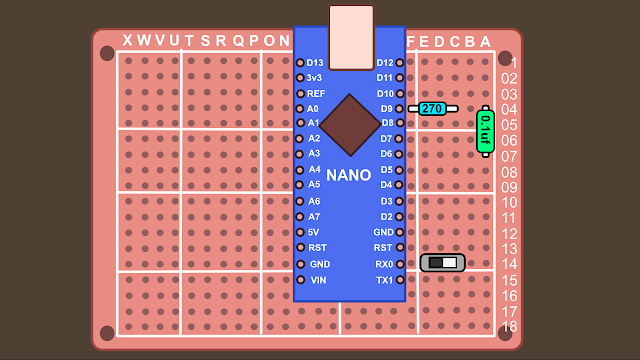
x1 Arduino Nano with usb cable $3.69 The 'brain' of our synth

It was pointed out to me that this pot is silent until the last few millimetres and then suddenly the volume is full. Try using a 100k version like this one instead.
x1 1M Ohm Logarithmic Taper Pot $0.50 Audio volume pot (use 100k)

x6 10K Ohm Linear Taper Pot $0.50 ($3) Synth control pots

x4 220 Ohm 1/4W 5% Resistor $0.01 ($0.10) Resistors (10 pack)
x2 270 Ohm 1/4W 5% Resistor $0.01 ($0.10) Resistors (10 pack)
x1 100 Ohm 1/4W 5% Resistor $0.01 ($0.10) Resistors (10 pack)
x1 470 Ohm 1/4W 5% Resistor $0.01 ($0.10) Resistors (10 pack)


x1 3.5mm Mono Audio Jack $0.12 Audio Out jack
**Update** This above jack was not long enough to fit the 3mm-deep Perspex sheet, replaced with a slightly longer version;
x1 3.5mm Mono Audio Jack $0.22 Audio Out jack
Tip: You can also use a larger guitar audio jack if you'd prefer.

x1 0.1uf (100nf) Poly Cap $0.10 Poly Capacitor for audio

x1 Proto board $0.99 Solder board for parts to sit on
**Update** Unfortunately Tayda didn't sell the same board as I used so this one was used as a replacement. It's a lot bigger than the 5cm x 7cm board I used, but it's possible to trim it down: What you can do is get a box-knife and a metal ruler and score down the sides you want cut off, then place it over the edge of a table and snap it off. Use a marker to add the numbering and characters. If you don't want to do this, have a search on eBay for a more similar board. Here's a link to banggood selling some (another site I use with much success), however it looks like the numbers / and letters are reversed from the board I used, so you might want to search further. Here's an eBay link to similar boards


x5 AWG hook up wire Red $0.10 ($0.50) Red wire (150cm)
x5 AWG hook up wire White $0.10 ($0.50) White wire (150cm)
Ebay parts (Google it & you might find better prices closer to you/store pickup possibilities etc). If the listings have ended, search by component name and if it looks like the photo shown here, you should be OK;
Tip: You can get parts from China really really cheaply but delivery times of a month or more are very common. Also I guess for me personally, maybe 1 in 20 items tend to never arrive. Ebay has a great refund policy, but if something gets lost you might be looking at a two month wait until you get your hands on a part. If you've ordered the other parts from Tayda that will get to you in a week, you may find paying a little bit more from a same-country seller is well worth it.


x1 5pin MIDI Din Connector $0.99 Midi connector (ebay)
Parts Total: Tayda $11.92 / Ebay: $2.79
Total: $14.71 (without P&P)
Obviously postage will be different where you are in the world, but using the Tayda discount code hopefully everything will come to about $20... maybe $22, but I think it's better say $20 purely for the click-bait title. Let's agree to disagree OK?
What Else?
You'll need a soldering iron, solder, wire-cutters, pliers, wire-strippers (or use a sharp blade to expose wire). If you make a mistake soldering you might need a solder sucker. If you make lots of mistakes you might need a multi-meter. If you have none of these things, you can often pick them all up in starter kits.
The Case
You're free to put the synth in any case you like, although perhaps not metal as it can cause problems. Cheap options include an old lunch box or VHS tape case. Those dollar-store places often sell wooden boxes that can be used for a synth case. If you want to build a case like in the pictures, you might well have some spare wood lying about. If not, mine cost 3 Euros from an arts supply shop. You might be able to get them to cut it for you if you're lucky. I used a perspex sheet for the front panel, again from the arts shop for about 2 euros. I used a laser engraver for the panel text, but if you don't have one no worries, you could use a silver marker pen, or a label printer. Other things you might need are wood glue and a saw. Some screws? All things you should be able to get at a hardware store (or pay 3 times the price at an art supplies store).
 |
| No laser engraver? Here's another synth with labels from a label printer |
Knobs: There are loads of types to choose from, here's a Moog-style pack of ten for under 2 euros. Or some Dave Smith types for 1.40e.

2. The Code
Parts arrived? Lets start with testing the Arduino. First you'll need to download the Arduino IDE, which lets us upload the code from your computer to the Arduino Nano. Head over to the Arduino site and download the software for your pc/Mac/Linus computer. Go ahead and install it.
Installing Libraries
Update 19/09/24: Mozzi 2.0 has been released but might not work with the Helios code. I recommend using Mozzi V1 library for now, which you can find here: https://github.com/sensorium/Mozzi/tree/Mozzi_1
The code we are using requires some external libraries. Libraries let you use code that other people have written, letting you achieve stuff that you might not be able to do on your own (god knows I couldn't). Lets install them now.
To use MIDI with our synth, we need to download the library from 47 effects. Click the 'code' button, then download the zip file.
In the same way, go and download the zip file from the Mozzi synthesis library.
So now you should have two zip files waiting to be added to the Arduino software. Open the Arduino software, click 'Sketch' -> Include Library -> Add .Zip Library


Great, so now that's installed, lets connect the nano and upload some code. If you're having any problems, google it or use the Arduino forums. I promise you someone else will have had the same problem, and someone else will have the answer.
Connecting the Nano
Connect your Arduino Nano to the computer with the USB cable. Hopefully the software will auto-detect, but we still need to check. Go to Tools -> Board -> Arduino Nano. Now we choose the port (Tools->Port) and chose where the USB is plugged into (com1, com2, com3 etc). There's loads of tutorials online about this (aka better than I can write).
If you have problems uploading your code
You may need to install drivers, but hopefully not. The internet is your friend if you're having trouble. If you purchased your Arduino form Tayda, there's a link to drivers on the product page.
With the Nano plugged in, you're given the option to choose the processor (tools -> processor), you might find changing from atmega328p, to atmega328p(old boot-loader) will help.. To see if it's working, we'll upload our first software program (called a 'sketch' in Arduino speak)
Our First Sketch: Blink

Choose:
The program will now load into the Arduino software, you'll see this as code on the screen. Next we have to upload it to our Nano. Click the upload arrow on the software. The program will compile and then send it to your Arduino Nano (as long as the Nano is connected OK, and you've selected 'nano' as your board under tools etc). You'll get an error message if there's a problem (if so google about connecting an Arduino to your computer). If it's successful you'll see a 'done uploading' sign. The sketch 'Blink' turns the built in LED on the Nano light on and off every second. If you see the 'done uploading' message and the LED on the Nano flashing, you know your board is working. This is good!
Playing with the code
Just to show the computer who's boss, we'll change the code ever so slightly. In the blink sketch page, change the two parts of the code that say delay(1000) to delay(500). This will flash the light every half second. The code looks like this;
// the loop function runs over and over again forever
void loop() {
digitalWrite(LED_BUILTIN, HIGH); // turn the LED on (HIGH is the voltage level)
delay(1000); // wait for a second
digitalWrite(LED_BUILTIN, LOW); // turn the LED off by making the voltage LOW
delay(1000); // wait for a second
}
...Those bits that say '1000' you should change to '500' like this;
// the loop function runs over and over again forever
void loop() {
digitalWrite(LED_BUILTIN, HIGH); // turn the LED on (HIGH is the voltage level)
delay(500); // wait for a second
digitalWrite(LED_BUILTIN, LOW); // turn the LED off by making the voltage LOW
delay(500); // wait for a second
}
Upload the new code and check the LED. It should now be flashing twice as fast as before. Congratulations, you're now a programmer!
Upload the Synth Code
Good stuff, we now know the Arduino is working, so we can upload the synth code.
Head over to my github page and download the zip file. Extract the file on your computer; we need the file called helios4_6.ino (Arduino uses .ino files). Save it in a location you can find again on your computer (maybe in an documents/Arduino projects folder?).
Then go to the Arduino IDE software File -> Open, choose the .ino file and it should load into the Aduino IDE window. Now press the upload button... the magic the code should upload to your Arduino Nano. That's all we need to do the genie is now in the bottle. Now we can start putting the synth together.
Code Explanation
There's a great explanation over on the Mozzi website about a simple sketch - it explains the basic setup of how everything works. Also, because we installed the Mozzi library we can view lots of example code ->

The synth we are building started as one of these examples... I think the first one used was a Mozzi-Midi-Input sketch. Then combined that with an oscillator sketch. Then added the filter sketch, envelopes etc. Basically, all I've done is assign pots to commands in the code. It might seem daunting at first, but if I can do it, there's a very good chance you can too.
If you're interested in learning more, each part of the code is explained elsewhere in the following links, as is building the synth on a temporary breadboard;
...But you don't need to know any of this stuff to build the synth, although maybe in the future you might want to learn a little bit more (and help improve the code).
3. Electronics
Now we're going to put all the parts we ordered together... but we'll also quickly make the front panel (so we have something to hold the parts while we solder).
Front Panel

Panel Layout

Drilling the Panel
Drill bit sizes;

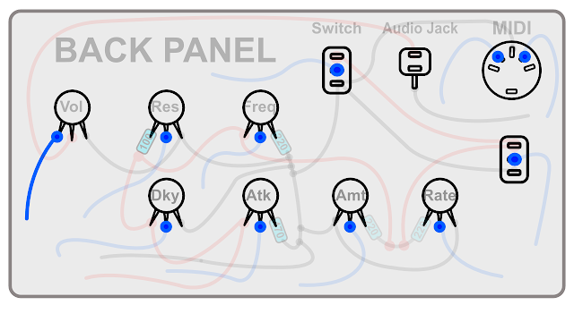
Then the back panel will look like this;

Start Soldering


A quick test (if you have a multi-meter)...
 |
| The green areas will beep, but not the red. |
Back to Soldering

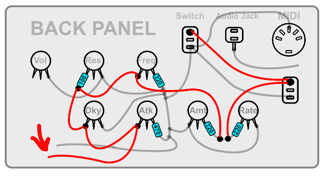
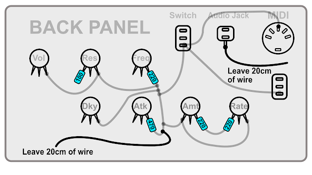
Now solder the next wires (again leave 20cm of wire on the one cable that isn't joined to anything). If you have a multimeter, check the Vol to Audio Jack. Then hold a connector to the two connections side of the resistor of the 'res', and see if you get a beep at freq, dky, atk, the switches and the middle of the Amt/Rate.


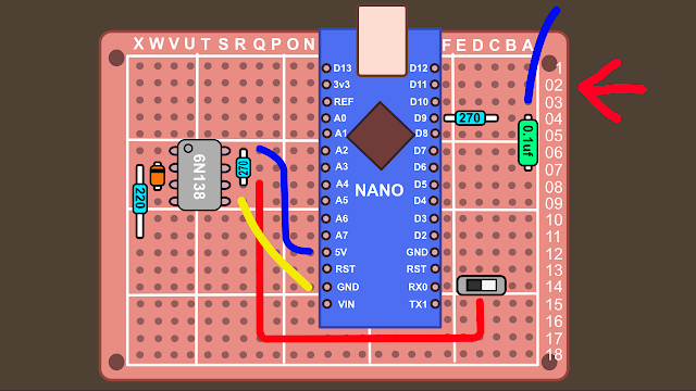
Making the proto-board:

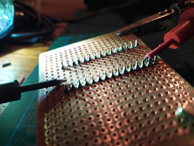
Now flip it over and solder all the legs to the board (the helping hands tool can come in handy here, or if not use a bit of tape to hold the Arduino down). Start with the corners to hold it into place. Make sure you don't accidentally solder any of the legs together:

Once soldered, using the multi-meter in continuity mode, check that none of the legs have accidentally been soldered together (put each multi-meter connector on the legs next to each-other and make sure there's no beep). If you hear a beep you may need to use a solder sucker to remove the excess solder. Sometimes the solder can get so close it looks like it's touching the other leg but it actually isn't.


Audio Out Section


 |
| Using the legs to jump to different areas |

The MIDI circuit
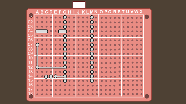


Easy right? Your board should now look like this:


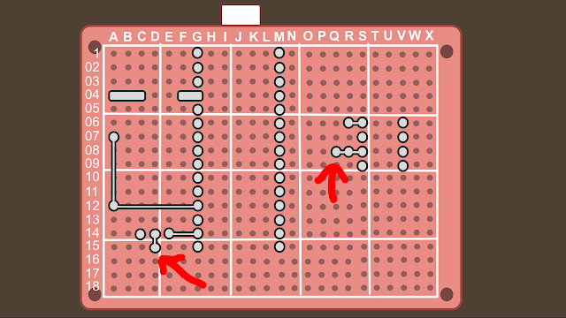


Now we add a 220 ohm resistor to X7 and X11:


And then solder it together;


Solder them in place:

Joining The Front Panel to the Proto-Board
Then you solder it:


..solder it in place - make sure you get the correct pin soldered (look closely on the board for the direction of the connection:

That plugs in O12:


OK, so we're almost finished (the second time I've said that now) we just have a few wires from the pots left to solder.

We shall be using pins: A0, A1, A2, A3, A4 and A5. Why not A6 and A7 you may ask, well...
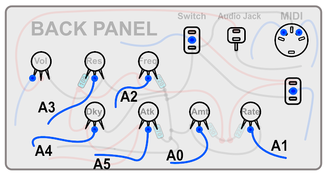

Connected underneath;

We're nearly Finished (This time I promise)
Ok, I forgot to get you to wire up the switches. Then we're finished. I promise. Let's do that now.We'll start with the LFO switch;

This wire connects to F10:

...and is soldered against the nano pin:

Now for the Wave Switch:


And then then solder to the nano pin:

 |
| Back view of synth - spaghetti junction! |
 |
| Finished view of the proto-board (Note: wire colors don't match examples) |
 |
| Your board should look a little like this (Note: might not exactly match examples) |
Now go get a beer.
Right, the synth is now complete - time now to give it a try. Is it working? Congratulations! Time for another beer. It's not working? Time to for some problem solving;
Troubleshooting Guide
Just remember that every part used is a potential problem waiting to spoil your fun, but hopefully we're going to get to the bottom of any faults. Lets break different problems down into categories;
1. Code:
The code definitely works (other people have confirmed this). Did you check the 'blink' sketch is working on your Arduino (the one where a light flashes on and off)? If not go back & read the code section of this guide again and get that working.
The switch is set incorrectly: Now that your synth is soldered, you maybe have to change the switch position (the one found on the proto-board) to get it to upload. From memory I believe the switch has to be pointing away from the nano to upload code, and closer to the nano to play the MIDI keyboard. Try reversing this if it's still not working.
Once the blink sketch is working, you can be fairly certain the problem isn't with the Arduino.
The only other problem you might have if you copy and paste the synth code and either you miss some of it, or your browser adds some extra (unseen) characters. Download the .ino file from my github (download everything as a zip). Then open the .ino file directly with the Arduino IDE. Once it's confirmed its uploaded OK, you can be pretty sure the code/Arduino are working correctly.
A few people have had problems with the midi switch. If you have a multimeter check for continuity on the switch legs. Only two pins should beep and one shouldn't. If all 3 beep that's the problem. If you don't have a multimeter you could desolder the switch and join the two connections closest to the Arduino.
2. MIDI connection
The proto-board switch is set correctly. You're playing the synth with a MIDI keyboard. Have you used this keyboard before and can confirm it works? How about the MIDI cable? And is it plugged in correctly? From the keyboard it should leave from the MIDI-OUT port and go into the DIY synth (which is MIDI-IN).
3. Power
You need to plug in the synth with the USB cable. Plug it into a mobile phone power supply, or maybe a laptop port (these can add noise to the audio). The Arduino should have a red power LED that lights up.
4. Is the Volume turned up/down?
It seems simple, but it has caught me out before! Also, there's a chance I've made you solder the volume pot in reverse, so maybe try turning it all the way down just in case.
5. There's a problem with this guide:
While I've tried really hard to write everything down without errors, it's entirely possible I've missed something. If you're having a problem leave a comment and I can update the guide with any fixes. Also leave a comment if you notice any mistakes. Thanks.
6. You've done something wrong:
Along with me making a mistake with the guide, this is probably the most likely cause for problems. We've made a lot of connections with the solder, and just one mistake could stop the whole thing. Check the following;
Dry Solder: Sometimes there can be 'dry' solder connections, where the part is connected but not really. You could try re-soldering/re-flowing these connections, or use a multi-meter in continuity mode to confirm they are good.
Accidental joins: It's possible some pins have accidentally been bridged while soldering. Again, use a multi-meter to check and de-solder any problems.
You've used different parts: If you know what you're doing then that's fine, but if you've used different parts without really knowing what they do, then this may have caused a problem. If you've used an Arduino Uno instead of a Nano, be aware the pins are in different places on the board (TX and RX pin I believe).
The Diode is the wrong way: Check the black line is facing the correct direction. The diode needs to face the correct way to work (while the resistors and capacitor we used on the board will work in either direction, known as having no 'polarity').
You've joined the wrong wires: Check check check! Look through the guide and confirm everything is correct.
The Audio jack isn't wired correctly: Check!
The LED light on the the Arduino Nano is showing midi is being sent, but I'm not getting Audio: If I had to guess it might be you've wired the audio pot wrong (or I've told you to do something wrong; other people have reported back success so hopefully not). If the midi light is lighting when you're pressing keys, then that part would appear to be working. Start with the simple things first: try turning the volume pot at different levels while playing the keys. Try this with all the knobs and buttons just to be sure. If that doesn't work, double check your connections around pin 9 of the Arduino nano... it should lead to a resistor and capacitor - this is where the audio leaves the Nano, then it goes to the volume pot, then to the audio jack. If you can't see a problem there then it's time to check the audio jack... the most likely candidate. Are the wires correct? Perhaps they need reversing? Are the jack connections the same in the photos? Perhaps the jack has been screwed in upside down (ie so the top leg is now bottom etc). Hopefully you'll find the problem. If you have a multi-meter you can check in continuity mode (the buzzer mode) that the bottom audio jack pin is going to ground... put one connector on the bottom jack, then the other connector on the Arduino nano pin that says 'gnd'. Hopefully it should beep.
7. There's a fault with one of your parts:
Maybe you left the soldering iron too close to a part for too long? I've never had it happen, but if you think you've mangled the soldering then look for burnt parts. Perhaps it was never working in the first place? While it's possible, it's also quite rare, even for dirt cheap parts. It's far more likely you've made a mistake somewhere else. If you've checked everything else is ok, you could start swapping out parts, or start checking voltages etc with the multi-meter. If you don't know how to do this, there are no doubt good YouTube videos/guides for you to learn from. You could also get into synth repair through this route, so while it's frustrating your synth isn't yet working, you are at least learning some new skills.
8. Wiggle
Try wiggling the wires to see if it suddenly starts working. That's the sign of a bad connection somewhere, or possibly a break in the wire.
9. Find a friend
If all else fails find someone else to help you fix it. If you don't know anyone personally you could try a local hack-space or friendly University department. If they know a little about electronics, you'll probably only have to show them the hand drawn schematic found at the top of this guide.
10. Try Running The Test Code
Tom Reid very nicely commented that he'd written some code to check the connections of the synth (copy & upload the blue code text into the Arduino IDE, and also open the serial monitor to view the results);
Great project and works well. I did knock together a short test program which checks all the switches and Pots. It gives an IDE monitor display so you can see the states and voltage. If you want a copy to post then you are more than welcome to post it.
Apologies for the delay - I need to add some comments into the code. Here is the code The test program checks the 2 switches and 6 controls. Also it generates a tone on the output socket. Compilied on IDE 1.8.42
>>>>>>>
/*
Test program for checking Pots, switches and Audio circuit
The program is designed to read the 6 volume controls and the 2 switches(LFO/WAV).
Yes I could have down this program cleaner with FOR loops, arrays etc - but it is only test program and took 20 minutes to knock up
Please feel to modify and improve on it.
Key elements the tester output will show on the monitor display
Note make sure switch is set to LOAD.
Switches
Wave Switch select0 Sq or Saw
LFO Switch select0 ON or OFF
Pots - set all Pots fully counter clockwise looking straight on to front panel
LFO RATE - Rate- clockwise increase volatage
LFO Rate - Amount - clockwies Voltage decreases
Filter-- Cutoff - clockwies Voltage decreases
Filter-- Res - clockwies Voltage increases
Envekope - Attack - clockwies Voltage decreases
Envelope - Release - Filter- clockwies Voltage increases
Audio output generates a Signal every
*/
//#include
float Volt0; // LFO Amount
float Volt1; // LFO Rate
float Volt2; // Filter cutoff
float Volt3; // Filter Res
float Volt4; // Envelope Release
float Volt5; // Envelope Attack
//wiring pins defined for the NANO version
int LFO;
int WAV;
int LFOPin = 3;
int WAVPin = 2;
void setup() {
// initialize serial communication at 9600 bits per second:
Serial.begin(9600);
pinMode(A0, INPUT);
pinMode(A1, INPUT);
pinMode(A2, INPUT);
pinMode(A3, INPUT);
pinMode(A4, INPUT);
pinMode(A5, INPUT);
pinMode(LFOPin, INPUT);
pinMode(WAVPin, INPUT);
pinMode(9,OUTPUT);
}
// the loop routine runs over and over again forever:
void loop()
{
// read the input on analog pin 0-5:
Volt0 = analogRead(A0);
Volt1 = analogRead(A1);
Volt2 = analogRead(A2);
Volt3 = analogRead(A3);
Volt4 = analogRead(A4);
Volt5 = analogRead(A5);
// Convert the analog reading (which goes from 0 - 1023) to a voltage (0 - 5V):
Volt0 = Volt0 * (5.0 / 1023.0); //LFO amount
Volt1 = Volt1 * (5.0 / 1023.0); // LFO Rate
Volt2 = Volt2 * (5.0 / 1023.0); //Filter Cutoff
Volt3 = Volt3 * (5.0 / 1023.0); //Filter Res
Volt4 = Volt4 * (5.0 / 1023.0); // Envelope Release
Volt5 = Volt5 * (5.0 / 1023.0); // Envelope Attack
LFO = digitalRead(LFOPin); // on/oFF
WAV = digitalRead(WAVPin); // Square or Saw wave
// print out the value
Serial.println(" LFO SW WAV SW LFO Rate LFO Amt Filter Cutoff Filter Res Env Rel Env Attack");
//Print switches
if ( LFO == 0) {
Serial.print(" OFF ");
}
else
{ Serial.print(" ON ");
}
if ( WAV == 0) {
Serial.print("SQR ");
}
else
{ Serial.print("SAW ");
}
Serial.print(Volt1);
Serial.print(" ");
Serial.print(Volt0);
Serial.print(" ");
Serial.print(Volt2);
Serial.print(" ");
Serial.print(Volt3);
Serial.print(" ");
Serial.print(Volt4);
Serial.print(" ");
Serial.print(Volt5);
Serial.println();
Serial.println();
tone(9,50,1000); //sound tone for short burst.-
delay(2000); // 2 seoond update on screen
// No test routing for the MIDI at this time - easy wiring so easy to troubleshoot
}
All good?
Hopefully you should have the synth up and running by now. If not, check the comments to see if any common problems have started to emerge. I'll try and help where I can, but obviously my time is limited.
4. Making a Case

You can make a case out of anything (VHS box!), but this is how I do it:
The wood used: mine cost 3 Euros from an arts supply shop in Berlin. It measures 9.0 x 250 x 500 mm. The same shop also sold perspex sheets for the front panel for 2 euros. These sheets measure 3 mm, 3.0 x 120 x 250 mm. Notice both the wood and perspex feature a 250mm measurement. This means if we cut the wood correctly it will already have a length exactly the same as the panel. This can save you some sawing, and you can also use the professionally cut sides at the front for a neater appearance (save your hack-saw work for the back!). If you don't have access to these supplies, I'm sure you can come up with you own method.
I used a laser engraver for the panel text, but if you don't have one no worries, you could use a silver marker pen, or a label printer. Other things you might need are wood glue and a saw. Some screws to join the panel to the wood. All things you should be able to get at a hardware store (or pay 3 times the price at an art supplies store).
Knobs: There are loads of types to choose from, here's a Moog-style pack of ten for under 2 euros. Or some Dave Smith types for 1.40e.
Ok, lets make the case:

12cm + 9mm + 9mm = 13.8cm
Tip: Depending how good you are with a saw, I'd cut each part 14cm long and then be prepared to sand down the excess.
Depth: I used 7cm as the depth of the wood. The nano and proto-board are about 5cm, so by using 7cm we give ourselves some room.
So you should now have wood like this:

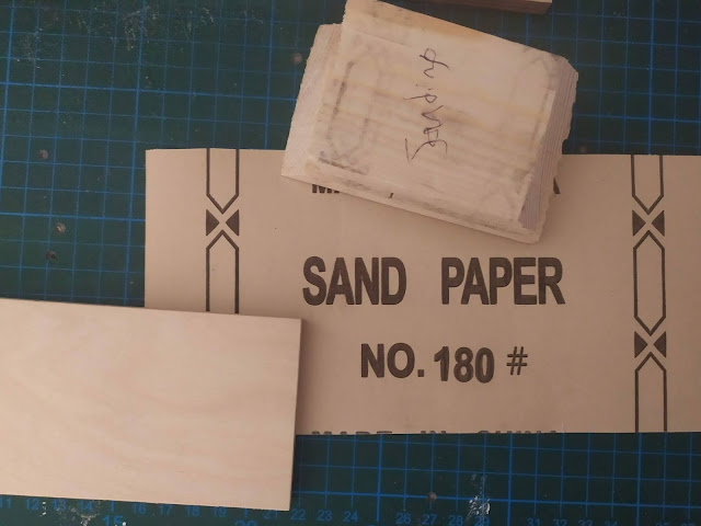
If you have the same wood skills as me, you'll probably have a few rough edges. You can use sanding paper or nail files to correct this:

Putting it all together:
We'll need wood glue. Remove all the components from the front panel and lay it down flat (or if you don't want to take the parts out: lay down four books and balance the panel in the middle, so it lays flat with the knobs hanging freely in the middle).
Stand the wooden sides around it and glue them together. You want a good fit where the panel meets the wood, so either hold it in place or use string and tie it together. Wood glue dries pretty quickly (5 - 10 min), so you won't get too bored. Think of it as birthing the synth.
Tip: You can buy a strap spanner to hold the wood tightly together for you, but it's a luxury item that you can do without.

Wipe away any excess glue (especially on the outside, where it can effect varnishing the wood). Now we cut a strip of 1cm-ish squared wood, cut into four 6cm pieces:
Tip: You can buy precut 1cm x 1cm wood from the store

Glue each of these pieces to the corners, making a good connection with the wood and also the front panel (these are where we'll screw in our synth panel):

When finished our case should look like this:

Tip: If you find the center of the perspex a little wobbly when playing the synth you can glue another 1cm piece to the center top or bottom of the case. Do this after you've finished so you don't get in the way of components.
Wipe away the excess glue.
Our case should now look like this:

Sand down any over-hanging edges if you like, or any glue that has leaked out.
The synth could be finished if you want to keep the wood looking natural, if not we can remove the panel and start to stain it.
I use a Mahogany stain like this;

The wood is thirsty, so you'll need maybe 3 or 4 coats. Add each layer evenly.


Apply a small amount with an old rag and finely distribute:
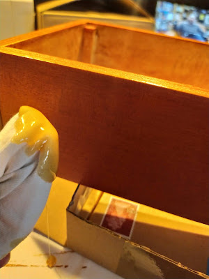


Tip: If you've missed some paint on the panel (like I have in the above picture on the LFO switch), you can still paint on the perspex, but just be aware it scratches easier this way.
 |
| Cable ties added. Still a bit of a mess! |

If you want a back cover you could cut some mdf board and screw it to the back. Mdf is an irritant to the lungs (possibly cancerous?), so wear a mask then wipe down your working area. Drill a hole for the usb port. You don't need a back cover (I probably won't bother for this build).
